Optical filtering method and apparatus

Active Publication Date: 2005-07-26
LUCENT TECH INC
View PDF9 Cites 1 Cited by
  • Summary
  • Abstract
  • Description
  • Claims
  • Application Information

AI Technical Summary

Benefits of technology

[0008]In another embodiment of the invention an optical regenerator is provided comprising a nonlinear medium for encoding information from a first optical signal onto a periodically modulated second optical signal to generate a third optical signal, and an optical filter apparatus operatively coupled to the nonlinear medium for processing the third optical signal. The optical filter apparatus comprises a spectrum broadening device for spectrally dividing the third optical signal into a discrete set of spectral components on a discrete number of corresponding light channel

Problems solved by technology

Such devices are, however, limited in their ability to provide sign

Method used


Image

  • Optical filtering method and apparatus
  • Optical filtering method and apparatus
  • Optical filtering method and apparatus

Examples


Example

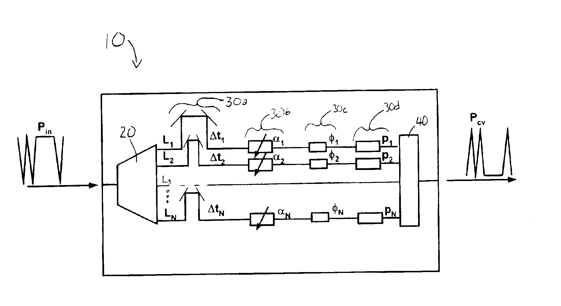
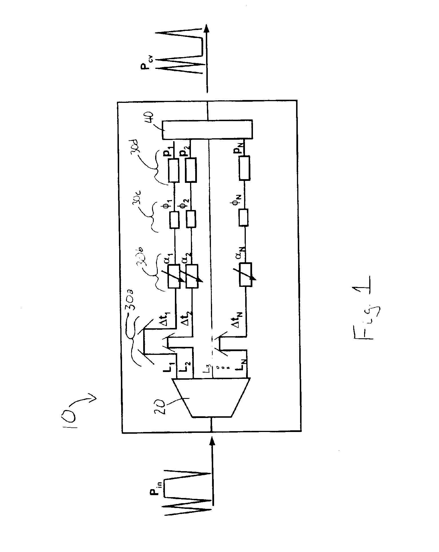
[0016]A schematic diagram of an optical filter apparatus 10 in accordance with one embodiment of the present invention is shown in FIG. 1. The optical filter 10 preferably comprises a spectrum broadening device 20 for spectrally broadening an optical signal (Pin) introduced into the optical filter 10. The spectrum broadening device 20 spectrally divides one or more channels or wavelengths of the optical signal (Pin) into a discrete set of spectral components. It can be understood by those skilled in the are that the optical signal (Pin) may be a wavelength multiplexed signal. The spectrum broadening device 20 may be realized as an optical prism, a grating, a waveguide grating router, a uniformly or non-uniformly index graded media or by other means known in the art.

[0017]A collector device operatively coupled to the spectrum broadening device 20 is also included in the optical filter 10 for collecting each of the discrete spectral components of the optical signal (Pin) on a discrete...


PUM


Abstract

An optical filter apparatus for processing an optical signal comprising a spectrum broadening device for spectrally dividing one or more channels of the optical signal into a discrete set of spectral components for each channel, a collector for collecting the spectral components on a discrete number of corresponding light channels, one or more processors for individually processing one or more of the spectral components on the light channels, and a combiner for recombining the spectral components on the light channels.

Description

TECHNICAL FIELD[0001]The present invention relates generally to the field of optical communications, and more particularly to a method and apparatus for optical filtering to perform functions such as signal format conversion, signal regeneration, and / or all-optical wavelength conversion.BACKGROUND OF THE INVENTION[0002]Fiber optic telecommunication networks use optical signals to transmit data and voice information. The data and voice information is typically generated in a transmitter, transmitted over an optical fiber network, switched in cross-connects and routers and finally converted back into an electrical signal in a receiver. During transmission of an optical signal, an optical filter may be used at several stages. For example, an optical filter may be used in a transmitter to provide signal format conversion. In a transparent network, optical filters might be necessary to regenerate the signal during transmission or to perform all-optical wavelength conversion to avoid wave...

Claims


Application Information

Patent Timeline
IPC IPC(8): H04B10/17G02F2/00G02F1/35H04B10/00H04J14/00H04J14/02
CPCH04B10/299
Inventor LEUTHOLD, JUERGMAROM, DAN MARKNEILSON, DAVID THOMASRYF, ROLAND
Owner LUCENT TECH INC
Why Eureka
Try Eureka