DETAILED DESCRIPTION OF THE DRAWINGS
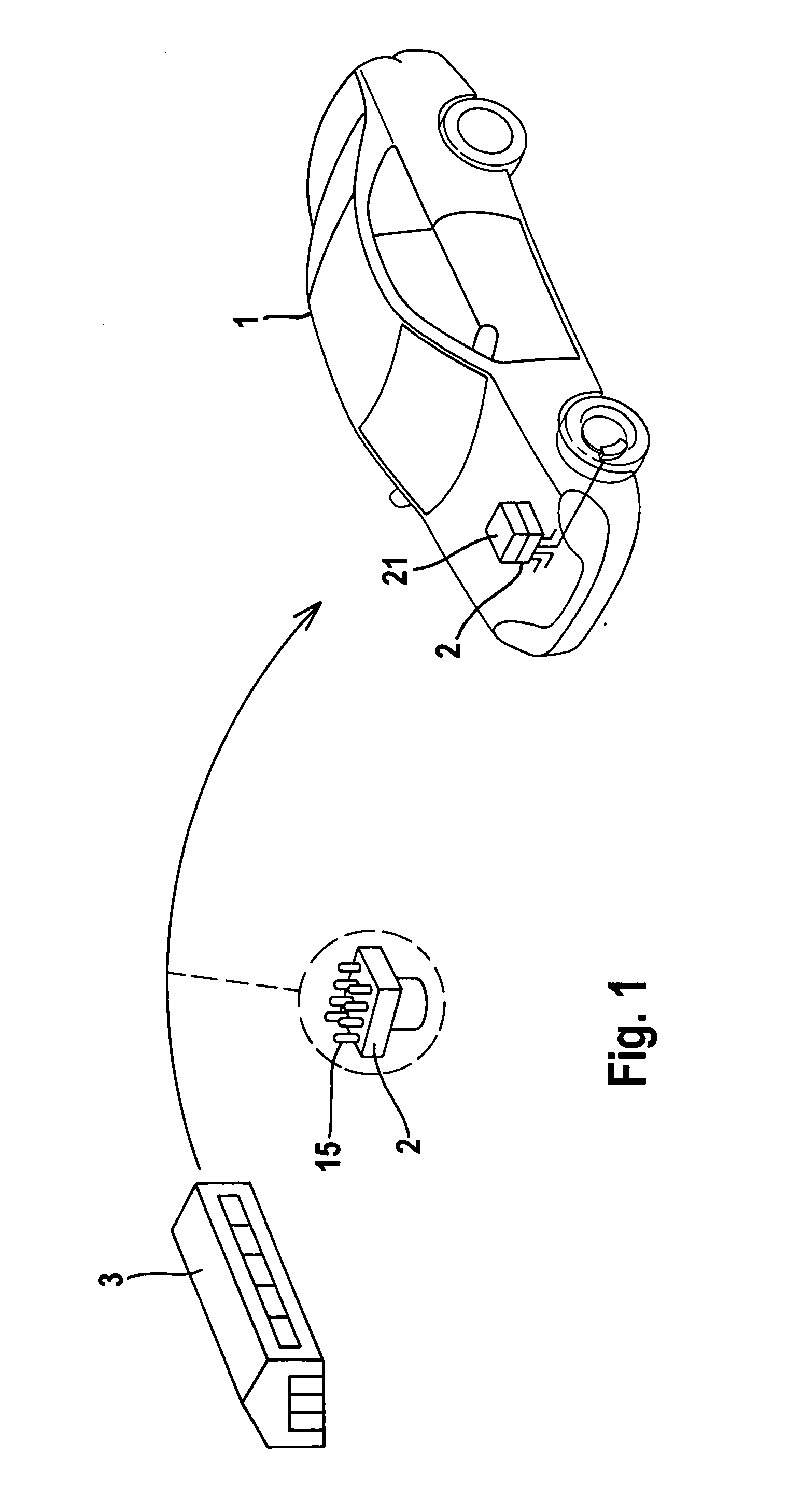
[0051]FIG. 1 explains the manufacturing process of a solenoid valve 15 for an electrohydraulic brake system 2 in a motor vehicle 1 with an ABS/ESP function. Initially, the solenoid valves are mechanically adjusted at manufacturing plant 3 after their manufacture according to the method of the invention in terms of a uniform opening current behavior, and they are then mounted into brake control unit 2. Due to residual tolerances, either existing or appearing in the course of time, it is possible, if a particularly high rate of precision in brake control is desired, to additionally carry out the subsequently described calibration process in the motor vehicle by way of the electronic controller 21, after the brake control unit 2 has been mounted into motor vehicle 1.
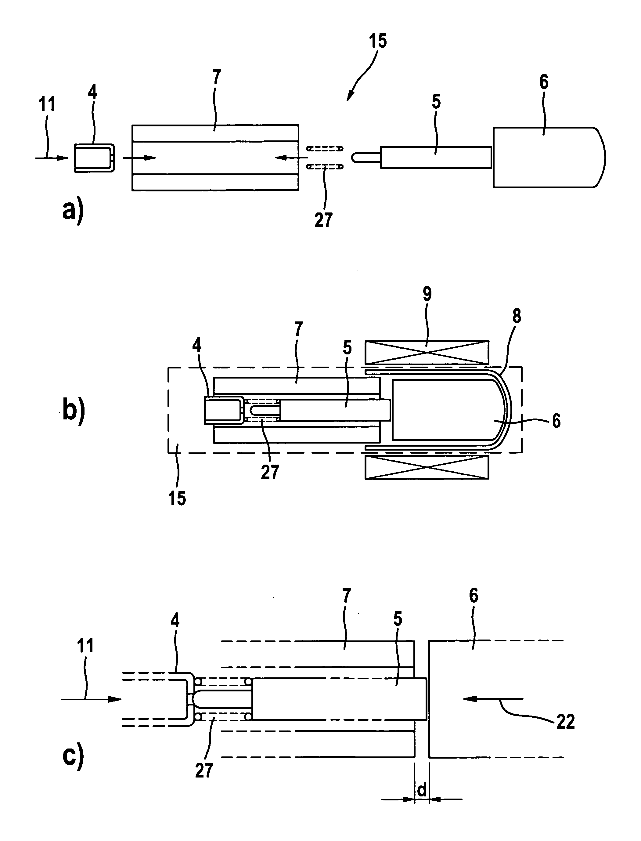
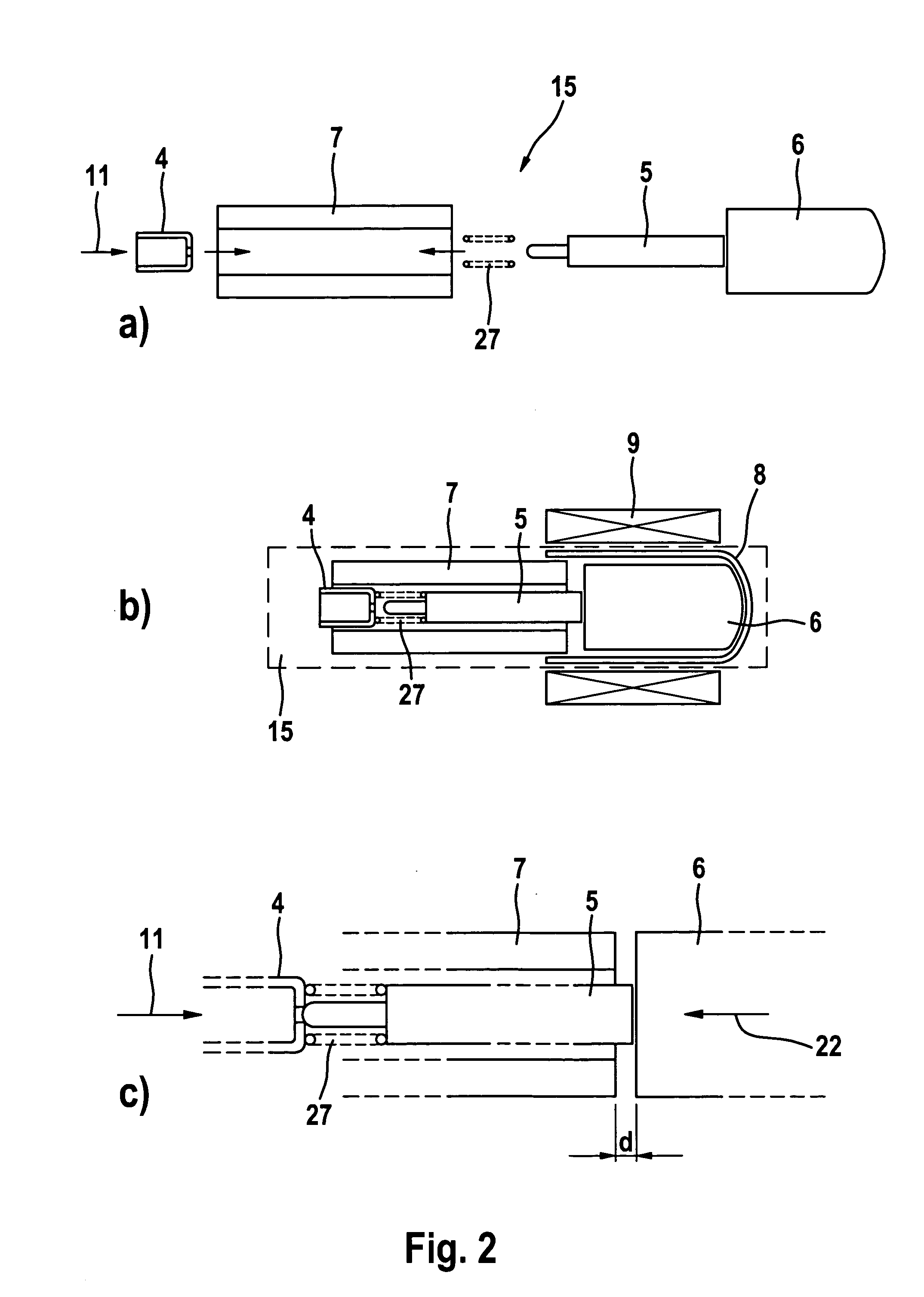
[0052]FIG. 2 shows a greatly schematic view of the design of a typical solenoid valve 15. Armature 6, housing 7, sleeve 8, and coil 9 are component parts of the electromagnetic arrangement which acts mechanically on the actual valve. To be more specific, the armature 6 is moved by the magnetic field of valve coil 9, thus acting mechanically on tappet 5. In the example of a normally open valve (NO valve), resetting spring 27 urges tappet 5 to adopt the open position when there is no magnetic field. Partial image c) shows the valve in the closed position, with the valve coil energized. Tappet 5 closes the opening in the valve seat 4 then. In the closing operation of the valve, armature 6 of the illustrated valve will approach housing 7, yet does not fully touch it. The remaining space between armature and housing is referred to as residual air slot d. According to the method described herein, the residual air slot d is adjusted by a displacement of valve seat 4 in the direction of arrow 11. This is done by considering the magnetic resistance in the closed valve position or by considering the opening current which can be found out from the defined excitation of the exciter coil 9 as will be described hereinbelow.
[0053] A second adjustment is performed in the open position of the valve. Armature 6 abuts on sleeve 8 when the valve is fully opened. The distance between completely closed position and completely opened position is referred to as tappet stroke and can be determined by a comparing consideration of the magnetic resistance in the opened position and in the closed position. The tappet stroke can be adjusted by displacement of sleeve 8.
[0054] Calibration Process in the Motor Vehicle
[0055] The above-mentioned calibration process in motor vehicle 1 is executed automatically in the electronic control unit 21 of the brake control unit and is used to calculate the opening current characteristic curves in each individual valve required for the valve flow control. One special feature of this calibration operation is that the actual calibration operation is carried out without pressurization of the valves. Therefore, the calibration operation is at any time self-supporting and can be executed independently of a workshop visit. The spring force is determined individually in this example. To begin with, the coil current I of the normally open solenoid valve 15 is gradually increased (in each case when enabling and disabling the valve current). Starting with a defined current the valve will close, armature 6 moves in the direction of the arrow 22 (FIG. 2c). The movement of the armature causes a reduction of the air slot between armature 6 and housing 7 and, hence, a measurable change of the total magnetic resistance Rm and, thus, also the inductance L L = N 2 R m , Φ = N × I R m
[0056] will apply then (N=number of windings of the coil, Φ=magnetic flux).
[0057] At the time of commencement of the movement of armature 6, there is a condition of equilibrium between the magnetic force Fmagn and the spring force Fspring acting on the armature, with the differential pressure ΔP=0: F spring = F magn = 1 2 * μ 0 * A armature * Φ 2 ,
[0058] (μ0=permeability constant of the air, Aarmature=armature surface). Thus, the spring force Fspring can be calculated from the magnetic flux Φ in consideration of the armature surface Aarmature. The tolerance-induced deviations of the spring forces which are measured this way can then be stored in a memory of controller 21.
[0059] The schematic representation in FIG. 3 shows a press 12 used to adjust the valve seat 4 of the valve 15. Press 12 comprises in its upper part a press accommodation 13 into which the valve 15 can be inserted. Integrated in valve accommodation 13 is exciter coil 9 for actuating the valve 15. Further, valve accommodation 13 comprises an outside iron core 14 onto which additional windings of a measuring coil 23 are wound. The flux in the magnetic circuit can be determined by means of measuring coil 23 in a particularly simple fashion.
[0060] Press tappet 16 is guided axially in the bottom part of the press so as to be displaceable in the direction of the arrow 19. The position of press tappet 16 can be adjusted by way of drive 17 using spindle 18. The absolute position of tappet 16 can be predetermined by an electric signal by way of electric input 20. To impress the valve seat 4 in housing 7, the press tappet is moved continuously in the direction of the arrow 19 at speed v = Δ X Δ t .
Exciter coil 9 is energized with a current according to a predetermined pattern (e.g. saw-tooth pattern, etc.), and the current has adopted a value which is changed in such a fashion, depending on whether the valve is initially opened or initially closed, that the valve is operated. The pattern is favorably designed in such a way that the valve is operated repeatedly in regular intervals (clockwise actuation).
[0061] The closed control circuit for the adjustment of the electromagnetic property is represented in FIG. 4. Press control electronics 24 produces a correcting variable ΔX/Δt predefining the press-in speed for press 12 and being sent to the input 20. Valve 15 is compressed in response to this signal. By feedback of an electromagnetic quantity 26 of the valve through line 25, a control loop develops in conjunction with the press which allows controlling the desired electromagnetic quantity of the valve in a particularly accurate manner by press electronics 24. As is illustrated in the box in FIG. 4, the electromagnetic quantity 26 fed back can be either the induced voltage Uind measured at exciter coil 9 or at separate measuring coil 23, or an electronically determined integral value ∫Uind of this quantity.
[0062] The integral value ∫Uind is proportional to the magnetic flux so that a flux control is realized herein. In case that the induced voltage is transmitted through line 25, it is required that the integral is produced in the electronics 24 prior to the actual control operation. Alternatively, the present valve holding current Ihold or the valve opening current Iopen can be transmitted as a controlled variable through line 25 to electronics 24.
[0063] An example for defining the valve tappet stroke 1 is subsequently described. The physical interrelationships explained hereinbelow are made the basis for the following calculation of the tappet stroke: U ind = - N * ⅆ Φ ⅆ t and Φ = - 1 N ∫ 0 t U ind ⅆ t .
[0064] When the valve current I is disabled, there will be a change of the magnetic flux Φ in valve 15 which causes an induction voltage Uind at exciter coil 9 or measuring coil 23. The total magnetic resistance RM can be measured in the open and closed condition of the valve. It is composed of the magnetic resistance of the air slot at the armature R M air = l μ 0 * A armature ,
which depends on the position of the armature, where Aarmature is the magnetically effective surface of the armature 6 which is specific for the line of products of the valve, and reference numeral 1 designates the tappet stroke. The actual method of measurement does not establish the value for RMair directly, but uses a measurement of the magnetic resistance when the valve is completely opened and a subtraction of the magnetic resistance of the closed valve. Consequently, the tappet stroke 1 may be defined this way alone from a measurement of the electromagnetic properties.
[0065] In the example described hereinabove, the valve is always completely closed or completely opened during the measurement of the magnetic resistance. An example for an adjustment method with clock-controlled valve opening will be described in the following. Initially, valve seat 4 is shifted into housing 7 for adjusting the air slot d when the valve is closed so that the magnetic resistance of the closed valve will continuously increase. The current in the exciter coil is at first higher than the closing current of the valve. When the press is compressed at constant speed, the valve will be opened at repeated times, that means clockwise, by way of the current in the exciter coil 9, and the valve opening current is determined as this occurs. It is possible to determine the valve opening current by considering the time variation of the induction voltage and/or the exciter coil voltage and/or the coil current because a measurable peak in the voltage and current variation of the coils arranged in the magnetic flux circuit results during the movement of the valve armature 6 that occurs in this case. The valve opening current of the valve can be determined in a defined present air slot adjustment from the range of the current that flows at the time of the peak. The determined opening current is transmitted to control unit 24 in punctual manner. The punctual or clocked determination takes place with a measuring frequency which is so high that a quasi-continuous control signal is available for the adjustment of the press.
[0066] The above explanations relate to a valve which is normally open (NO valve). The described method can be employed in a similar way also for valves which are normally closed (NC valves).