Mechanism for adjusting a rotary angle of an LCD

a technology of rotary angle and lcd, which is applied in the direction of machine supports, instruments, electrical apparatus casings/cabinets/drawers, etc., can solve the problems of inconvenience, trouble, and inability to maintain the angular position, and achieve the effect of maintaining the stability of operation

Inactive Publication Date: 2007-02-08
POSIFLEX TECH
View PDF18 Cites 9 Cited by
  • Summary
  • Abstract
  • Description
  • Claims
  • Application Information

AI Technical Summary

Benefits of technology

[0006] An object of the present invention is to provide a mechanism for adjusting a rotary angle of an LCD which can adjust and firmly maintain the right and left rotating angle of the LCD for enabling the LCD to maintain stability in operation.
[0008] Another object of the present invention is to provide a mechanism for adjusting a rotary angle of an LCD which can restrict the rotating scope of the LCD or release the restriction of the rotating scope of the LCD.

Problems solved by technology

However, the manner of simply adjusting and positioning the angle through the pivot results in unstable angular position.
When the LCD is employed as a touch panel, the force of a user's touch can sway or shift the LCD, which causes unstable operation and even causes the rotary angle to change, resulting in inconvenience and trouble in use.

Method used


Image

  • Mechanism for adjusting a rotary angle of an LCD
  • Mechanism for adjusting a rotary angle of an LCD
  • Mechanism for adjusting a rotary angle of an LCD

Examples


Embodiment Construction

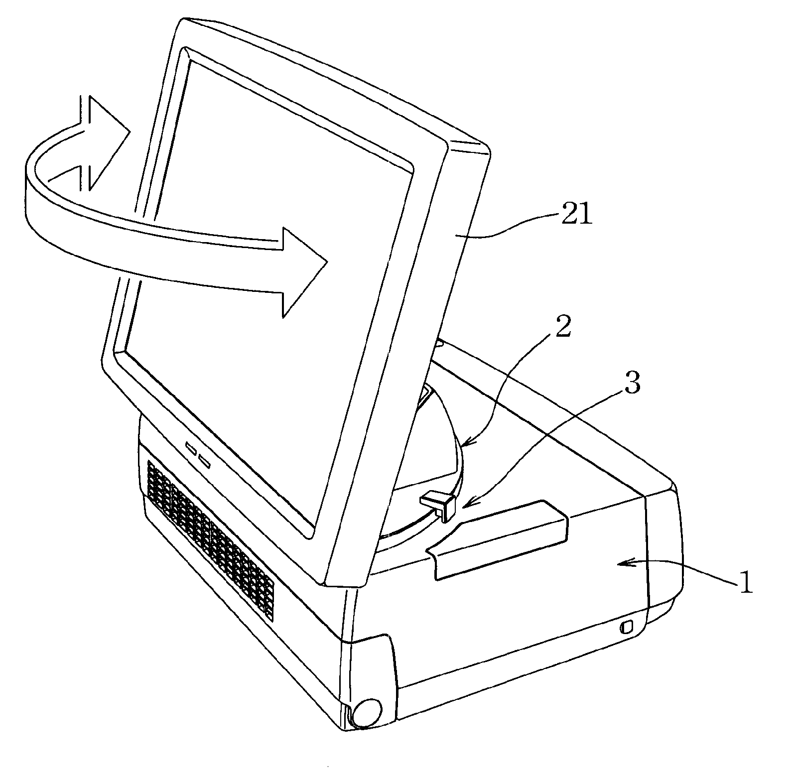
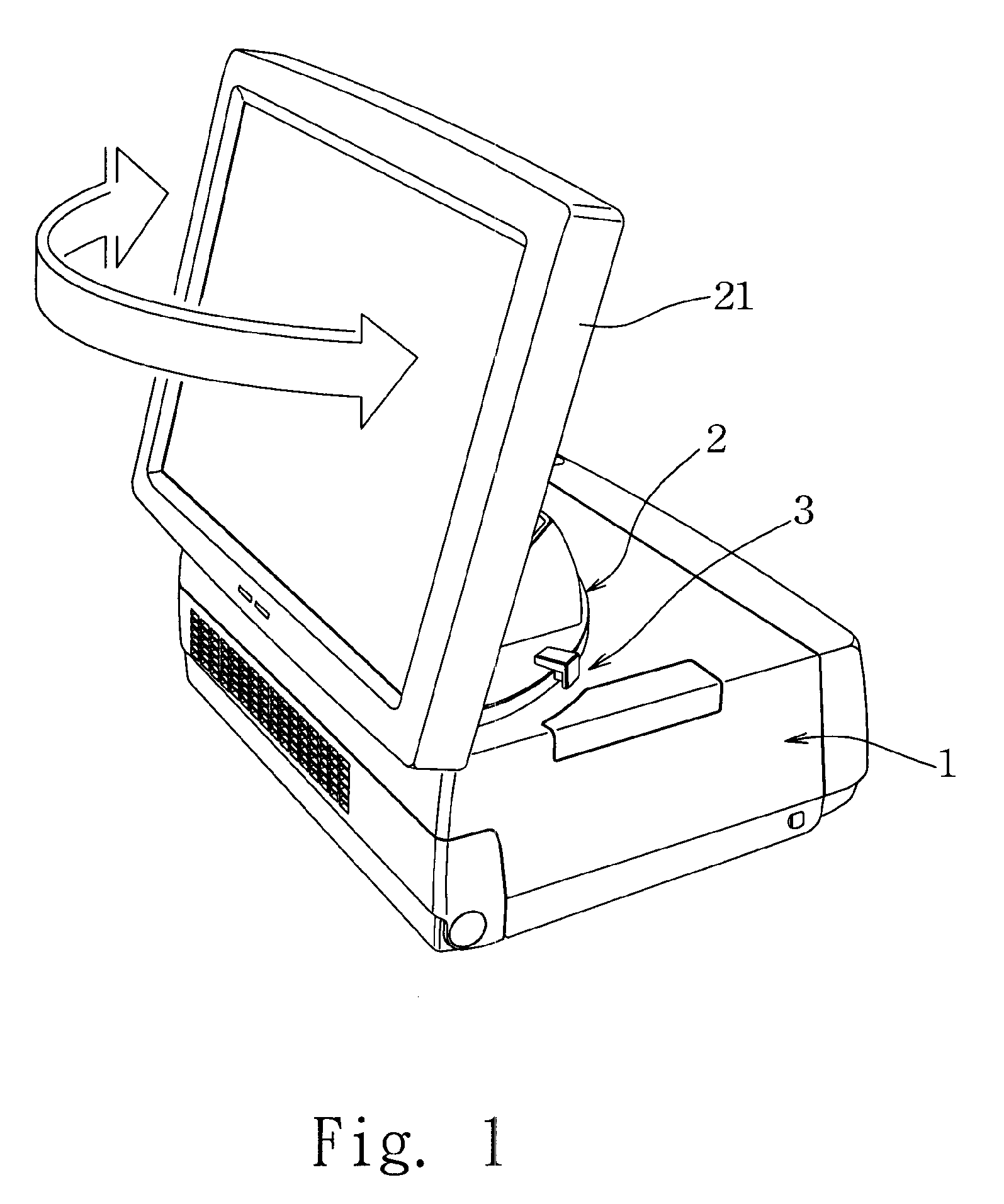
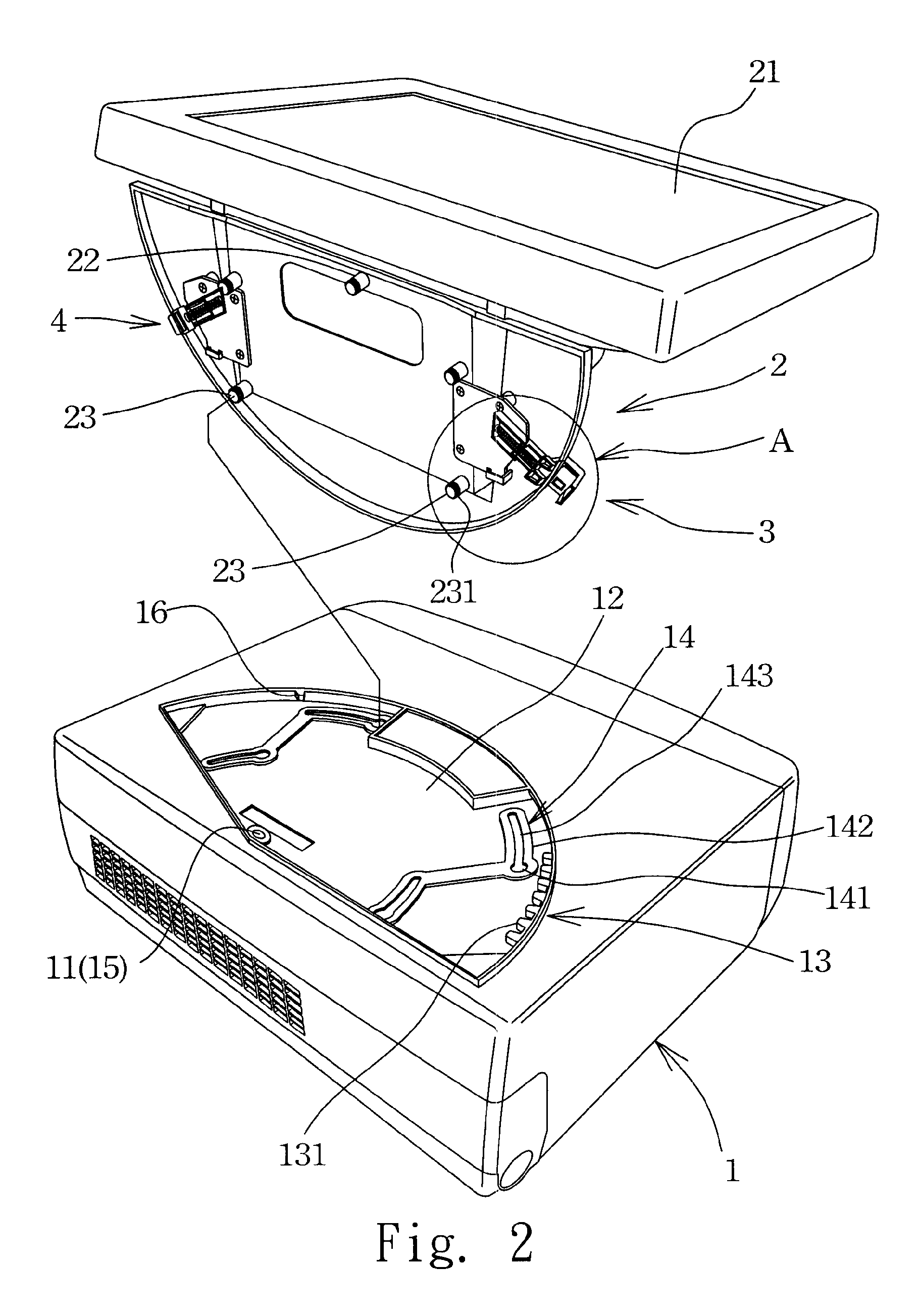
[0017] Referring to the above figures, a mechanism for adjusting a rotary angle of an LCD of the present invention includes a lower base 1, an upper base 2 and a positioning mechanism 3.

[0018] The lower base 1 is defined with a rotary center 11 at the top surface thereof. A sector recess 12 is defined in the top surface of the lower base with the rotary center being employed as the center of the sector. A portion of the inner edge of the sector recess is disposed with a rack 13 including a plurality of protruding teeth 131. The bottom surface of the sector recess is defined with at least two arcuate sliding grooves 14 (four arcuate sliding grooves are shown in the figures) which employ the rotary center 11 as the circular center thereof. The arcuate sliding grooves are in lateral symmetry which employs the rotary center 11 as the center thereof. An assembly hole 141 with a larger diameter is defined at an end of each arcuate sliding groove 14 for assembly or disassembly of a slidin...


PUM


Abstract

A mechanism for adjusting a rotary angle of an LCD includes: a lower base with a sector rack and arcuate sliding grooves disposed at the top surface thereof; an upper base disposed with an LCD at an upper portion thereof, the bottom surface of the upper base being disposed with sliding posts for movably engaging with the arcuate sliding grooves; and a positioning mechanism including a positioning spring and a positioning push button. The positioning spring constantly urges the positioning push button to mate with one of the protruding teeth of the rack, thereby positioning the rotary angle of the upper base and the LCD. When the positioning push button is inwardly pushed, the positioning push button is disengaged from the protruding tooth thereby enabling the LCD to rotate right and left. The adjusting mechanism further includes an inhibiting mechanism for restricting the rotating scope of the LCD.

Description

RELATED APPLICATIONS [0001] The present application is based on, and claims priority from, Taiwan Application Serial Number 94213516, filed Aug. 8, 2005, the disclosure of which is hereby incorporated by reference herein in its entirety. FIELD OF THE INVENTION [0002] The present invention relates to a mechanism for adjusting angle, and particularly to a mechanism for adjusting a rotary angle of an LCD (liquid crystal display) which conveniently adjusts the right and left rotating angle of the LCD and steadily maintains the adjusted rotary angle. BACKGROUND OF THE INVENTION [0003] A right and left rotary angle of an LCD needs to be adjusted to overcome its limited visual angle and to enable the LCD to be used as a touch panel. [0004] A rotary angle of an LCD is conventionally adjusted and maintained by pivotal engagement between the bottom of the LCD and a base. [0005] However, the manner of simply adjusting and positioning the angle through the pivot results in unstable angular posi...

Claims


Application Information

Patent Timeline
Patent Type & Authority Applications(United States)
IPC IPC(8): G06F1/16
CPCF16M11/08F16M11/22F16M2200/08F16M2200/024F16M2200/022
Inventor CHENG, TSUNG-KAN
Owner POSIFLEX TECH
Why Eureka
Try Eureka