Method, program product and apparatus for performing mask feature pitch decomposition for use in a multiple exposure process

a target pattern and mask technology, applied in the field of mask feature pitch decomposition and multiple exposure process, can solve the problems of inability to image individual features, inability to achieve near-term solutions, and high capital equipment costs, and no known systematic process or methodology regarding the process of decomposition or “coloring” target patterns

Active Publication Date: 2007-02-08
ASML NETHERLANDS BV
View PDF30 Cites 39 Cited by
  • Summary
  • Abstract
  • Description
  • Claims
  • Application Information

AI Technical Summary

Benefits of technology

[0018] The present invention provides important advantages over the prior art. Most importantly, the present invention provides a systematic approach for decomposing a target pattern into multiple exposure masks. While typically highly-skilled engineers were required to perform the decomposition of target patterns including complex 2-dimensional features so as to ensure the resulting image would properly correspond to the target pattern, the present invention provides a systematic approach for decomposing target patterns which allows even a novice designer to perform the decomposition process.

Problems solved by technology

These rules are set by processing and design limitations.
In order to print feature pitch below 108 nm, it is necessary to use shorter exposure wavelengths or higher NA, either of which can be quite an expensive capital equipment proposition and not feasible for a near term solution.
Such a technique is typically utilized when the target features are spaced so closely together that it is not possible to image the individual features.
While feature pitch decomposition for 1-dimensional features, such as illustrated in FIGS. 1a-1d, is generally well known by the lithography-engineering field, currently there is no known systematic process or methodology regarding how to decompose or “color” target patterns including complex and random 2D features.

Method used


Image

  • Method, program product and apparatus for performing mask feature pitch decomposition for use in a multiple exposure process
  • Method, program product and apparatus for performing mask feature pitch decomposition for use in a multiple exposure process
  • Method, program product and apparatus for performing mask feature pitch decomposition for use in a multiple exposure process

Examples


Embodiment Construction

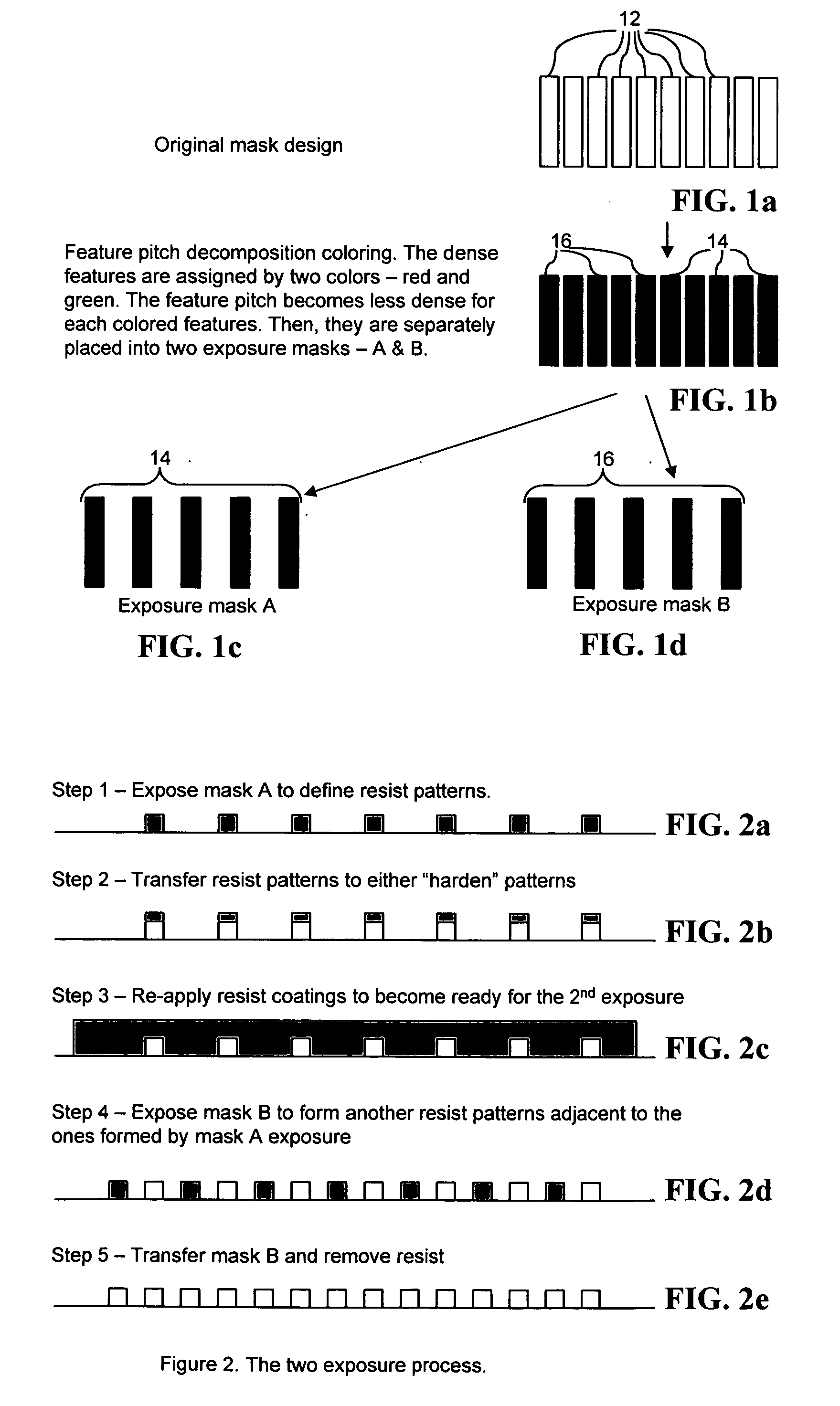
[0030] As explained in more detail below, the pattern decomposition process of the present invention systematically decomposes a target pattern so as to assign features (or portions thereof) of the target pattern to one of two (or more) exposure masks, which are illuminated separately in a multiple exposure process. Furthermore, as shown in the examples disclosed herein, the decomposition process of the present invention, when necessary, provides for decomposition of single geometry (i.e., feature) in the target pattern into multiple segments, which are then imaged in separate illumination processes.

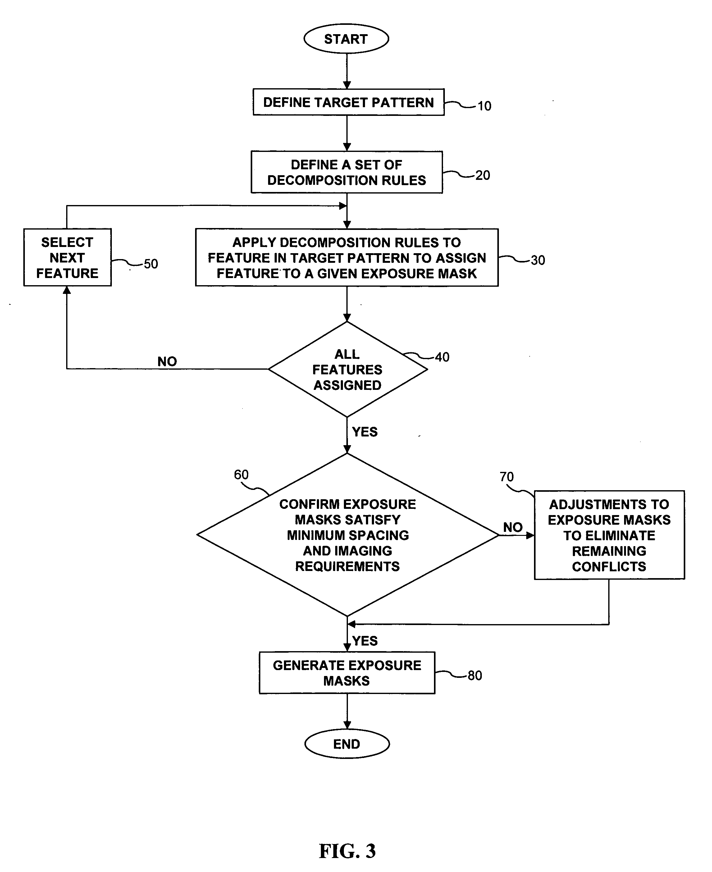
[0031] Referring to FIG. 3, which is an exemplary flowchart of a first embodiment of the decomposition process, the first step in the process (Step 10) is to define the target pattern (i.e., the pattern to be imaged on the substrate). The target pattern is typically described in a data format, such as “GDSII”, which is a standard data format. However, any other suitable data format can ...


PUM

PropertyMeasurementUnit
wavelengthsaaaaaaaaaa
critical dimensionaaaaaaaaaa
optical proximityaaaaaaaaaa

Abstract

A method for forming exposure masks for imaging a target pattern having features to be imaged on a substrate in a multi-exposure process. The method includes the steps of generating a set of decomposition rules defining whether a given feature of the target pattern is assigned to a first exposure mask or a second exposure mask; applying the decomposition rules to each of the features in the target pattern so as to assign each of the features in the target pattern to one of the first exposure mask or second exposure mask; and generating the first exposure mask and the second exposure mask containing the respective features assigned to each mask.

Description

PRIORITY INFORMATION [0001] This application claims priority to U.S. Provisional Application Ser. No. 60 / 692,574, which was filed on Jun. 22, 2005, the contents of which are hereby incorporated by reference in their entirety.TECHNICAL FIELD [0002] The technical field of the present invention relates generally to a method, program product and apparatus for performing a decomposition of a target pattern so as to allow the target pattern to be imaged utilizing multiple masks in a multiple illumination process. BACKGROUND OF THE INVENTION [0003] Lithographic apparatus can be used, for example, in the manufacture of integrated circuits (ICs). In such a case, the mask may contain a circuit pattern corresponding to an individual layer of the IC, and this pattern can be imaged onto a target portion (e.g., comprising one or more dies) on a substrate (silicon wafer) that has been coated with a layer of radiation-sensitive material (resist). In general, a single wafer will contain a whole netw...

Claims


Application Information

Patent Timeline
Patent Type & Authority Applications(United States)
IPC IPC(8): G03F1/00
CPCG03F7/70466G03F1/144G03F1/70
Inventor CHEN, JANG FUNGHSU, DUAN-FU STEPHENVAN DEN BROEKE, DOUGLASLAIDIG, THOMAS
Owner ASML NETHERLANDS BV
Why Eureka
Try Eureka