Control circuit using toggled activation to reduce inrush currents

a control circuit and toggle activation technology, applied in the field of electronic circuits, can solve the problems of underpowering and/or overloading the desired circuit, rated to power specifications lower than specific applications, and transformers mounted on the ground, etc., to achieve the effect of reducing costs and straightforward and modular design

Inactive Publication Date: 2007-02-08
CORE INDS MICHIGAN
View PDF22 Cites 18 Cited by
  • Summary
  • Abstract
  • Description
  • Claims
  • Application Information

AI Technical Summary

Benefits of technology

[0010] For example, the controller circuit can be part of a personal cooling system of an exercise machine, such as a treadmill. In such an example, the controller circuit can comprise a fan controller board, the electric devices may include one or more fans, and the electronic components may include a board-mounted transformer having tolerances near or below the inrush current generally present in powering on the fans of the personal cooling system. Some of the purposes for using the foregoing transformer include ensuring a more straightforward and modular design, reducing costs, and ensuring the fan controller board meets regulations for use in residential exercise machines.

Problems solved by technology

The drawback to board-mounted transformers, however, is that they can be rated to power specifications lower than specific applications require.
Accordingly, circuit designers often must choose between using circuit components that are not rated for certain inrush levels, thereby potentially underpowering and / or overloading the desired circuit, or using circuit components that add significant cost and complexity to a particular design.
In some applications, such as applications having significantly limited power and / or limited cost margins, use of the costly and complex circuit components can defeat the application at the design stage.
For example, in the design of exercise equipment, certain desirable features may have significant cost and design limitations, such as, for example, personal cooling systems including air flow mechanisms like fans.
When the design of such mechanisms use components rated to account for inrush currents, the added cost and complexity can dictate their removal from the design.

Method used


Image

  • Control circuit using toggled activation to reduce inrush currents
  • Control circuit using toggled activation to reduce inrush currents
  • Control circuit using toggled activation to reduce inrush currents

Examples


Embodiment Construction

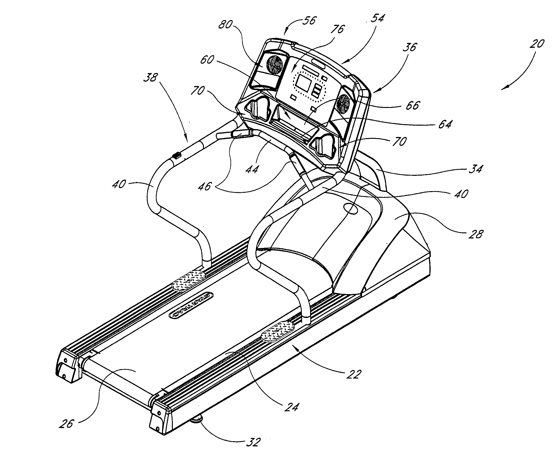
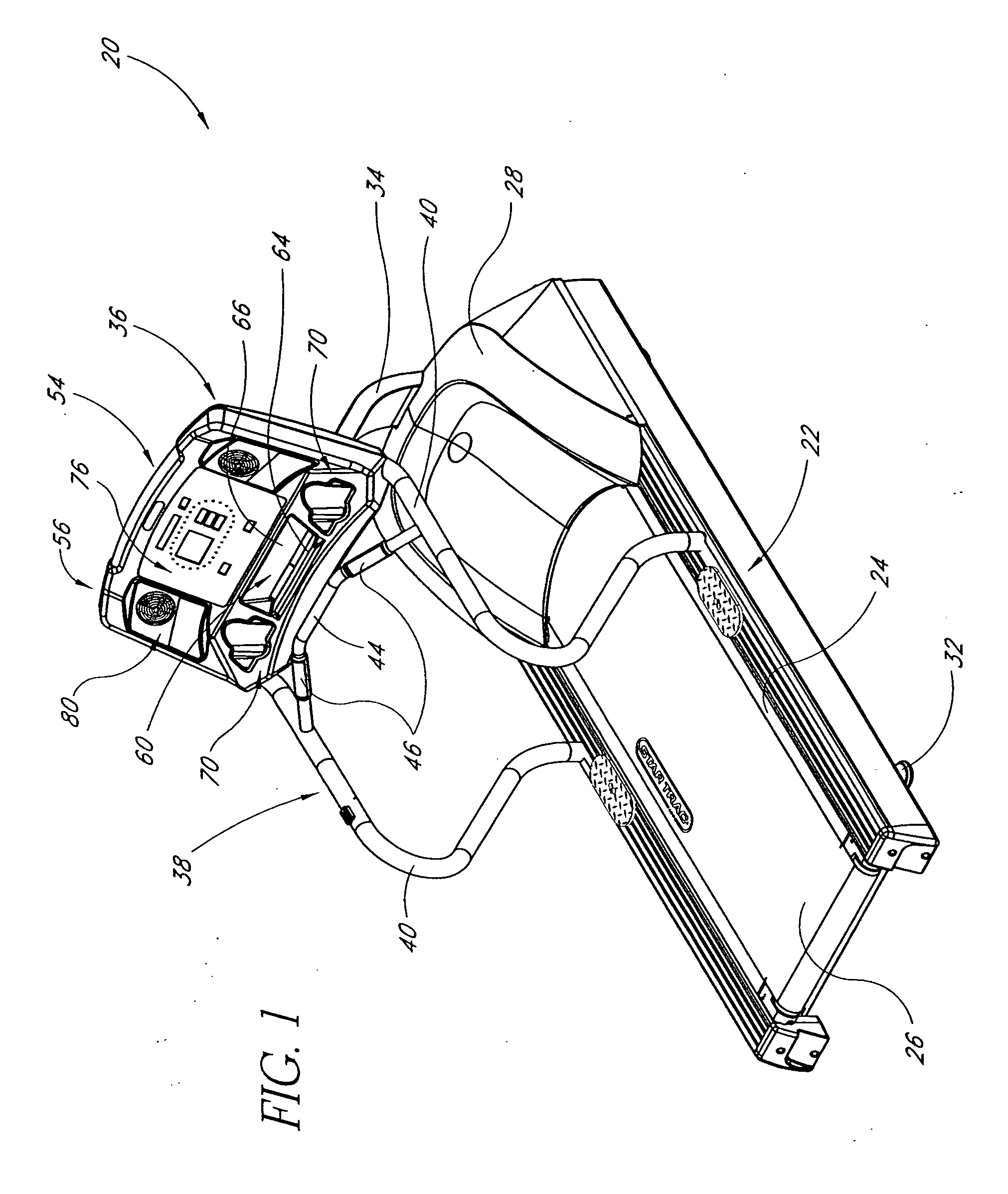
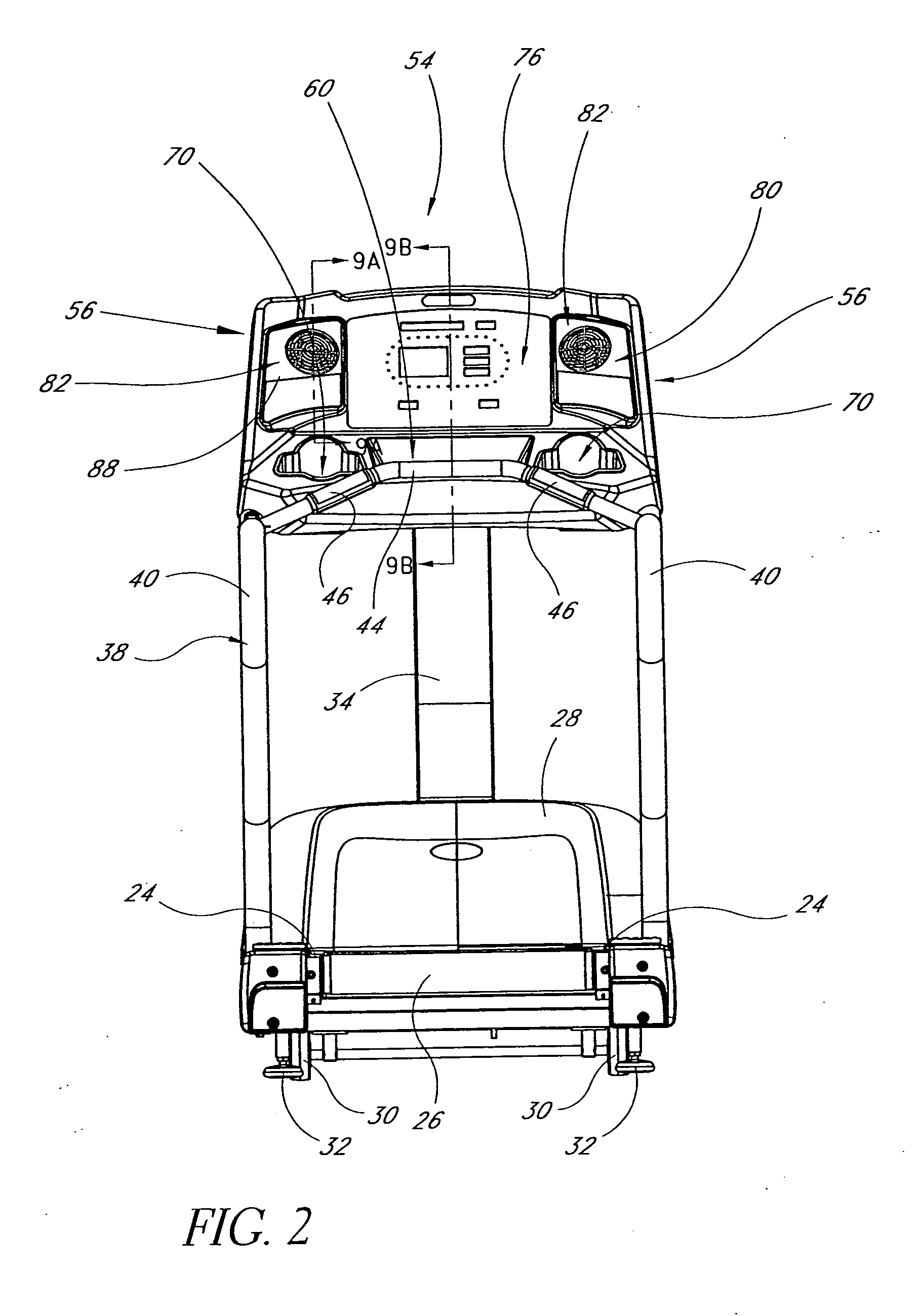
[0037] With reference now to FIGS. 1-6, a treadmill 20 that is arranged and configured in accordance with certain features, aspects and advantages of the present invention is illustrated therein. While various features of the present invention have been shown and will be described in the context of the treadmill 20, the present invention also can be used with other forms of exercise apparatus, such as, but not limited to, stair climbers, elliptical exercise machines, stationary bicycles, ski machines and the like.

[0038] The treadmill 20 generally comprises a frame assembly 22. The frame assembly 22 can have any suitable configuration. In one arrangement, the frame assembly 22 is formed by a number of tubular members that are secured together by, for instance, welding, brackets and / or fasteners. The frame assembly 22 generally defines a base structure of the treadmill 20.

[0039] A support surface 24 is connected to the frame assembly 22. The support surface 24 can be secured to the ...


PUM


Abstract

Aspects of the present invention include a controller circuit for an exercise machine, where the controller circuit includes a board mounted transformer having tolerances near or below the inrush current generally present in activating one or more cooling fans. According to one embodiment, the controller circuit attempts to power on a subsequent fan after the sum of the inrush or steady state current of presently operating fan or fans, and the inrush current generally associated with powering on the subsequent fan, is within the tolerances of the transformer.

Description

REFERENCE TO RELATED APPLICATION [0001] The present application is a divisional of U.S. patent application Ser. No. 10 / 299,648, filed Nov. 19, 2002, entitled “Control Circuit Using Toggled Activation to Reduce Inrush Currents,” which claims priority benefit under 35 U.S.C. § 119(e) of U.S. Provisional Application No. 60 / 399,336, filed Jul. 26, 2002, entitled “Cooling System for Exercise Machine.” The present application incorporates the foregoing disclosures herein by reference. [0002] The present application is also related to U.S. patent application Ser. No. 10 / 299,627, filed Nov. 19, 2002, entitled “Cooling System for Exercise Machine,” and U.S. patent application Ser. No. 10 / 299,625, filed Nov. 19, 2002, entitled “Maintenance Facilitating Exercise Machine Console,” the disclosures of which are hereby incorporated by reference in their entirety.BACKGROUND OF THE INVENTION [0003] 1. Field of the Invention [0004] The present invention relates to the field of electronic circuits. Mo...

Claims


Application Information

Patent Timeline
Patent Type & Authority Applications(United States)
IPC IPC(8): A63B22/02A63B24/00
CPCA63B22/02A63B24/00A63B2225/30A63B2225/687A63B2225/66A63B2225/682A63B2225/685A63B2225/50A63B2071/0658Y10S482/90
Inventor REYES, JAVIER J.WALLACE, GREGORY A.
Owner CORE INDS MICHIGAN
Why Eureka
Try Eureka