
Compliant diaphragm medical sensor and technique for using the same

a diaphragm and sensor technology, applied in the field of medical devices, can solve the problems of insufficient conformity or suppleness of materials used in their construction, discomfort of patients, and difficulty in achieving conformity

Inactive Publication Date: 2007-02-08
TYCO HEALTHCARE GRP LP
View PDF99 Cites 86 Cited by
  • Summary
  • Abstract
  • Description
  • Claims
  • Application Information

AI Technical Summary

Benefits of technology

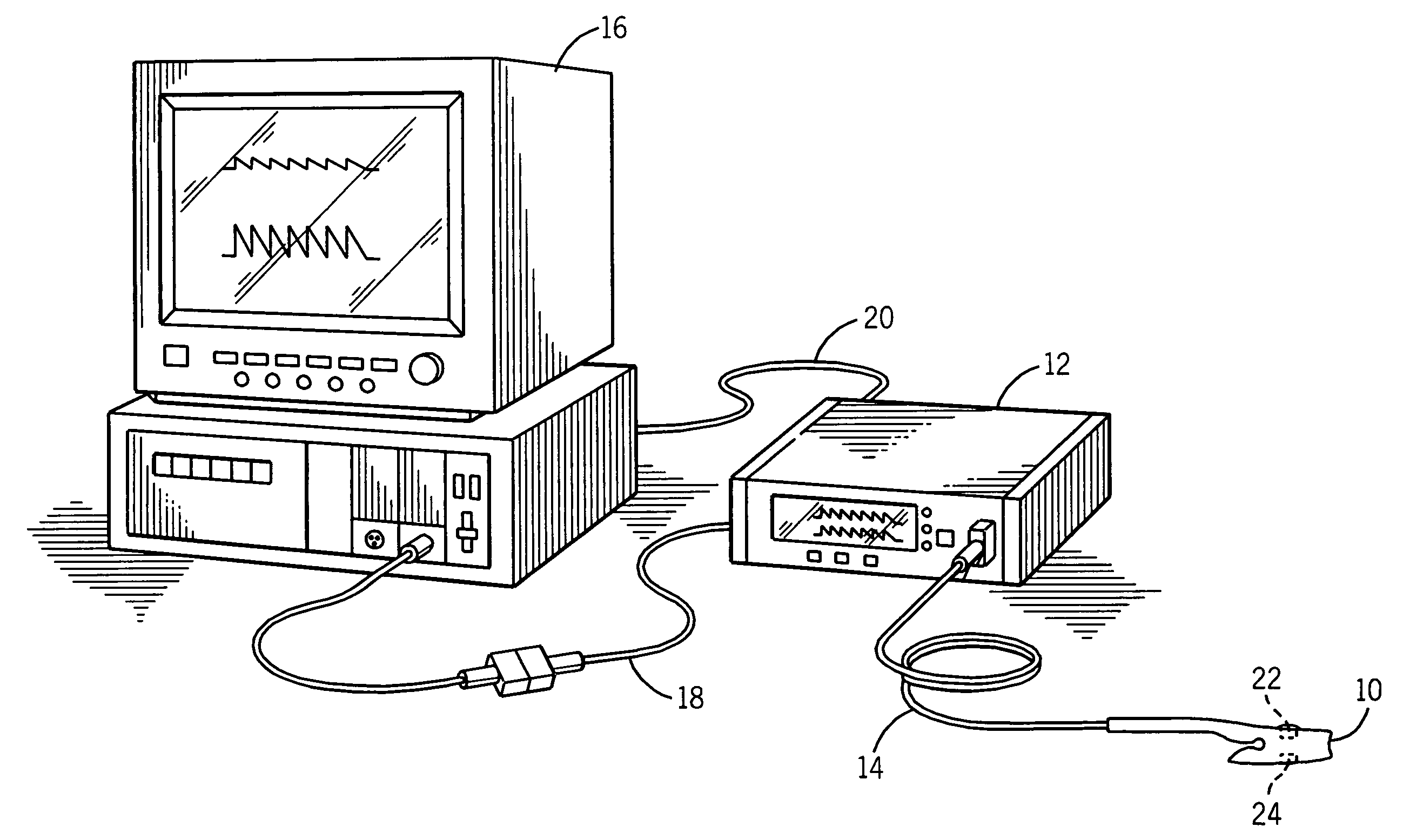
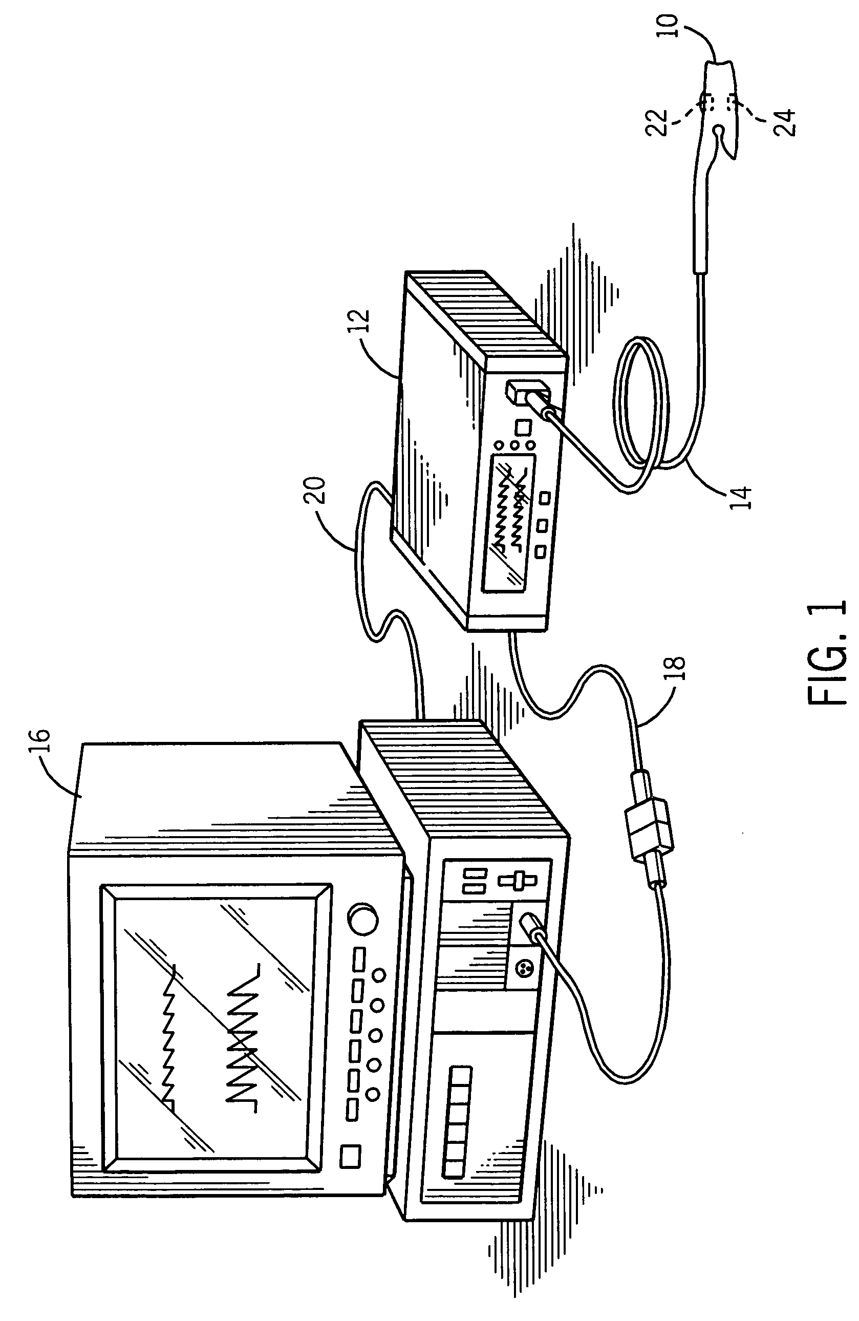
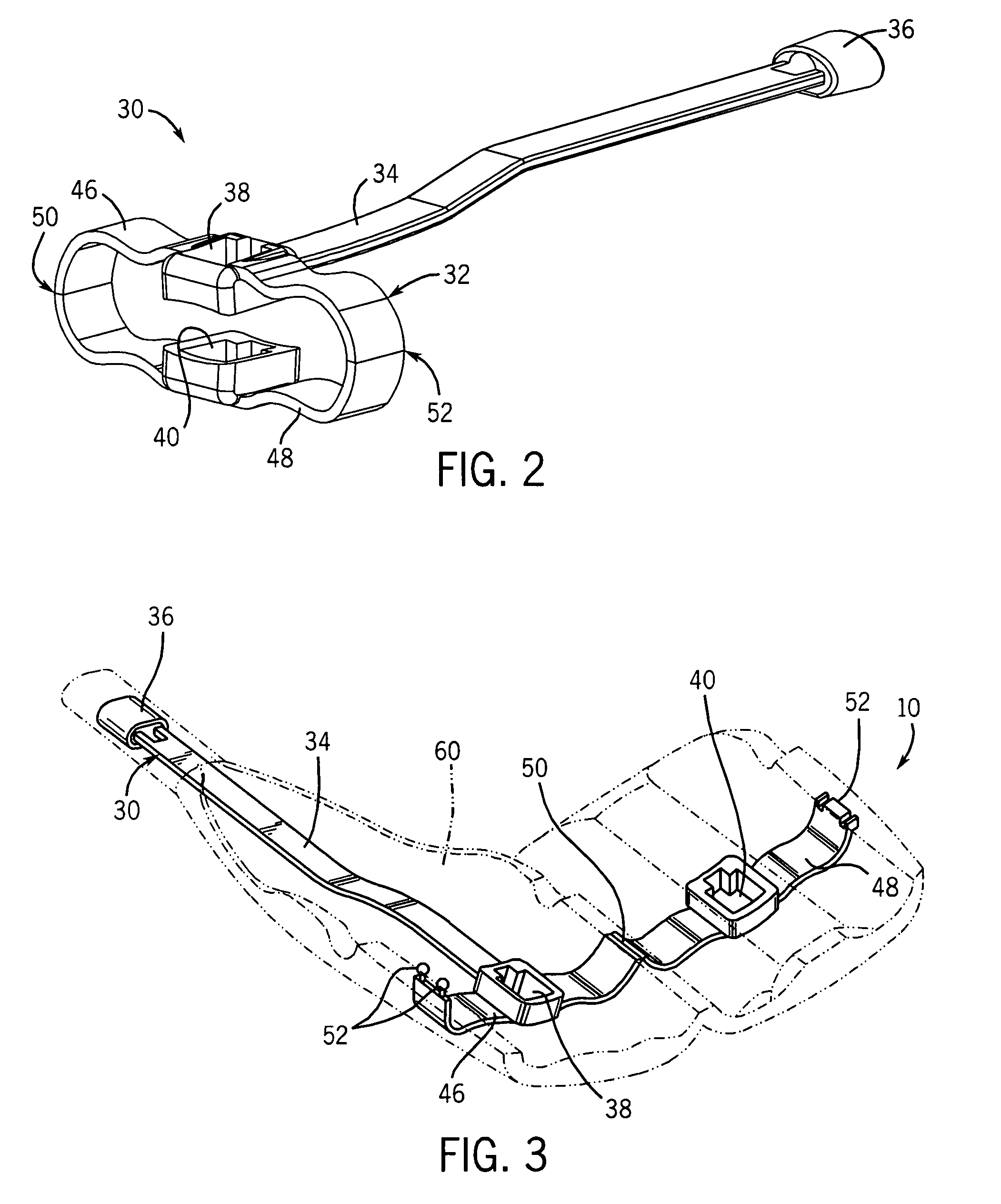
The invention is a sensor assembly that includes a frame with a loop structure and an emitter and detector on opposing sides of the loop structure. The frame is coated with a material that includes at least one diaphragm structure. The technical effect of this invention is that it allows for the sensors to detect movement along an axis between the emitter and detector, providing more accurate and reliable data. Additionally, the frame provides support for the overlying coating, ensuring the diaphragm structures are formed properly. The method for manufacturing the frame includes forming a frame with at least one loop structure and then coating it with a material that includes at least one diaphragm structure.

Problems solved by technology

Such reusable sensors, however, may be uncomfortable for the patient for various reasons.
For example, the materials used in their construction may not be adequately compliant or supple or the structural features may include angles or edges.
Such a conforming fit may be difficult to achieve over a range of patient physiologies without adjustment or excessive attention on the part of medical personnel.
In addition, lack of a tight or secure fit may allow light from the environment to reach the photodetecting elements of the sensor.
Such environmental light is not related to a physiological characteristic of the patient and may, therefore, introduce error into the measurements derived using data obtained with the sensor.
However, in sensors having a multi-part construction, as is typical in reusable pulse oximeter sensors, it may be difficult to perform such a quick and / or routine cleaning.
Such cleaning is labor intensive and may be impractical in a typical hospital or clinic environment.

Method used


Image

  • Compliant diaphragm medical sensor and technique for using the same
  • Compliant diaphragm medical sensor and technique for using the same
  • Compliant diaphragm medical sensor and technique for using the same

Examples


Embodiment Construction

[0026] One or more specific embodiments of the present invention will be described below. In an effort to provide a concise description of these embodiments, not all features of an actual implementation are described in the specification. It should be appreciated that in the development of any such actual implementation, as in any engineering or design project, numerous implementation-specific decisions must be made to achieve the developers' specific goals, such as compliance with system-related and business-related constraints, which may vary from one implementation to another. Moreover, it should be appreciated that such a development effort might be complex and time consuming, but would nevertheless be a routine undertaking of design, fabrication, and manufacture for those of ordinary skill having the benefit of this disclosure.

[0027] It is desirable to provide a comfortable and conformable reusable patient sensor, such as for use in pulse oximetry or other applications utilizi...


PUM

PropertyMeasurementUnit
near infrared wavelengthsaaaaaaaaaa
thermoplasticaaaaaaaaaa
metallicaaaaaaaaaa

Abstract

A sensor assembly is provided that includes a frame having a loop structure. An emitter and detector are disposed on opposite sides of the loop structure. A coating is provided over the frame. The coating includes at least one diaphragm structure disposed such that at least one of the emitter and detector can move along an axis running between the emitter and detector. The sensor may thereby be placed on a patient's finger, toe, and so forth to obtain pulse oximetry or other physiological measurements. A sensor frame and method of manufacturing the frame are also provided.

Description

CROSS-REFERENCE TO RELATED APPLICATION [0001] This application is a continuation of U.S. Application Number Ser. No. 11 / 199,345 filed Aug. 8, 2005, the disclosure of which is hereby incorporated by reference in its entirety.BACKGROUND OF THE INVENTION [0002] 1. Field of the Invention [0003] The present invention relates generally to medical devices and, more particularly, to sensors used for sensing physiological parameters of a patient. [0004] 2. Description of the Related Art [0005] This section is intended to introduce the reader to various aspects of art that may be related to various aspects of the present invention, which are described and / or claimed below. This discussion is believed to be helpful in providing the reader with background information to facilitate a better understanding of the various aspects of the present invention. Accordingly, it should be understood that these statements are to be read in this light, and not as admissions of prior art. [0006] In the field ...

Claims


Application Information

Patent Timeline
Patent Type & Authority Applications(United States)
IPC IPC(8): A61B5/00
CPCA61B5/14552A61B5/6826A61B5/6838Y10T29/49888Y10T29/49947Y10T29/49826Y10T29/49885Y10T156/10Y10T29/49002
Inventor EGHBAL, DARIUSCOAKLEY, JOSEPHMATLOCK, GEORGE L.RARIDAN, WILLIAM
Owner TYCO HEALTHCARE GRP LP
Learn More