Cold diaphragm with light blocking ring structure
A technology of light blocking ring and cold diaphragm, applied in the field of optical components, can solve the problems of large stray light cold diaphragm, unable to effectively remove stray light radiation, difficult to provide cold diaphragm, etc., and achieve the effect of simple production
- Summary
- Abstract
- Description
- Claims
- Application Information
AI Technical Summary
Problems solved by technology
Method used
Image
Examples
Embodiment 1
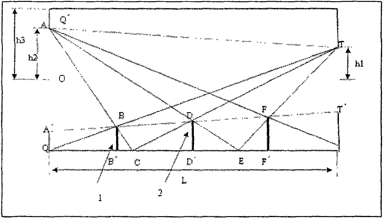
[0037] Embodiment 1: Cylindrical and light-blocking ring contour arrangement 1 (see Figure 6 )
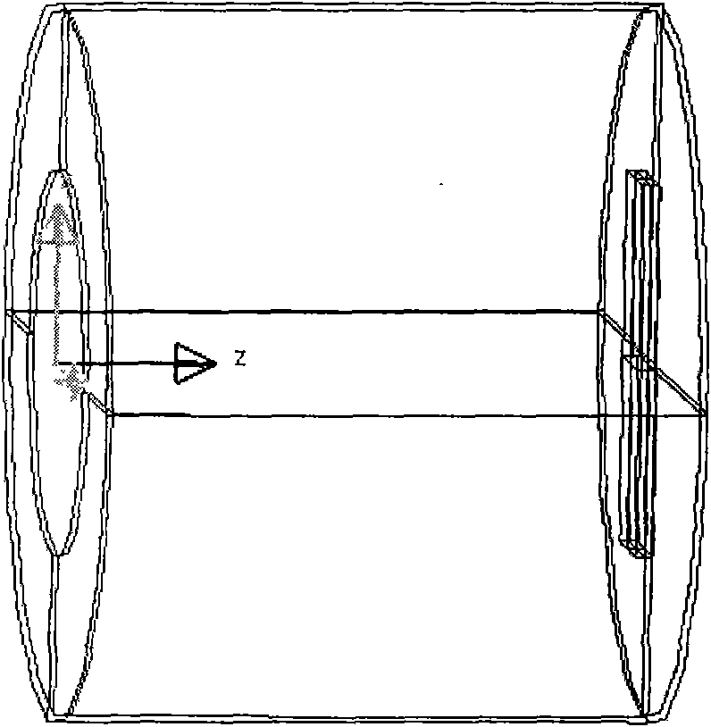
[0038] Here, the cold diaphragm is a cylindrical shape such as Figure 4 In 1 (its inner wall length L=19.3 mm, thickness is 2 mm, front end diameter QQ′=23.4 mm, rear end diameter PP′=23.4 mm), the entrance aperture is a circle such as Figure 4 4 of them (Aperture AA' = 12.8 mm), the detector is placed at the bottom as Figure 4 3 in (circumscribed circle diameter TT'=12.8 mm), QQ'=PP', AA'=TT'. The material is Kovar, and the inside is plated with a layer of black nickel with a thickness of 12μm (this thickness is ignored when calculating the light blocking ring). Detailed parameters are shown in Table 1. The design steps are: (see Figure 6 )
[0039] (1) Connect QT and intersect A'T' at point B, and cross B to make BB' perpendicular to QP', BB' is the height of the first light blocking ring, and QB' is the position of the first light blocking ring relative to the inner ...
Embodiment 2
[0055] Embodiment 2: Cylindrical and light-blocking ring contour arrangement 2 (see Figure 7 )
[0056] Here, the cold diaphragm is a cylindrical shape such as Figure 4 In 1 (its inner wall length L=19.3 mm, thickness is 2 mm, front end diameter QQ′=23.4 mm, rear end diameter PP′=23.4 mm), the entrance aperture is a circle such as Figure 4 4 (entrance aperture AA' = 12.8mm), the bottom end of the detector is placed as Figure 4 3 in (circumscribed circle diameter TT'=8 mm), QQ'=PP', AA'>TT'. The material is Kovar, and the inside is plated with a layer of black nickel with a thickness of 12μm (this thickness is ignored when calculating the light blocking ring). Detailed parameters are shown in Table 1. The design steps are: (see Figure 7 )
[0057] (1) Since TT′
[0058] (2) Connect QK and intersect A'K' at point B, and cross B to make BB' perpendi...
Embodiment 3
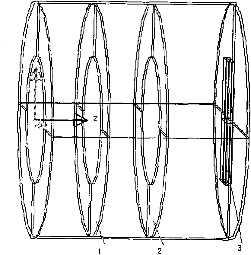
[0068] Embodiment 3: Cylindrical and light-blocking ring gradient arrangement (see Figure 8 )
[0069] Here, the cold diaphragm is a cylindrical shape such as Figure 4 In 1 (its inner wall length L=19.3 mm, thickness is 2 mm, front end diameter QQ′=23.4 mm, rear end diameter PP′=23.4 mm), the entrance aperture is a circle such as Figure 4 4 of them (Aperture AA' = 12.8 mm), the detector is placed at the bottom as Figure 4 3 in (circumscribed circle diameter TT'=8 mm), QQ'=PP', AA'>TT'. The material is Kovar, and the inside is plated with a layer of black nickel with a thickness of 12μm (this thickness is ignored when calculating the light blocking ring). See Table 1 for detailed parameters
[0070] The design steps are: (see Figure 8 )
[0071] (1) Connect QT and intersect A'T' at point B, and cross B to make BB' perpendicular to QP', BB' is the height of the first light blocking ring, and QB' is the position of the first light blocking ring relative to the inner ...
PUM
 Abstract
Description
Claims
Application Information
 - R&D
- Intellectual Property
- Life Sciences
- Materials
- Tech Scout
- Unparalleled Data Quality
- Higher Quality Content
- 60% Fewer Hallucinations
Browse by: Latest US Patents, China's latest patents, Technical Efficacy Thesaurus, Application Domain, Technology Topic, Popular Technical Reports.
© 2025 PatSnap. All rights reserved.Legal|Privacy policy|Modern Slavery Act Transparency Statement|Sitemap|About US| Contact US: help@patsnap.com


