Printer

a printing machine and printing head technology, applied in the field of printing machines, can solve the problems of disadvantageous reduction of printing density, disadvantageous adhesion of colored ink sheets to paper, and inability to reduce printing density, etc., to suppress density reduction and reduce time

Inactive Publication Date: 2007-02-15
FUNAI ELECTRIC CO LTD
View PDF5 Cites 2 Cited by
  • Summary
  • Abstract
  • Description
  • Claims
  • Application Information

AI Technical Summary

Benefits of technology

[0011] The present invention has been proposed in order to solve the aforementioned problems, and an object of the present invention is to provide a printer capable of reducing a time for increasing the temperature of a heating element to a proper level for starting printing beforehand and suppressing density reduction in an initial stage of printing.

Problems solved by technology

However, while the printers described in the aforementioned Japanese Patent Laying-Open Nos. 56-161182 and 9-216398 can increase the temperatures of the heating elements to proper levels during printing, each literature neither discloses nor suggests a method of increasing the temperature(s) of the heating element(s) to a proper level when the thermal head (print head) comes into contact with the paper to reduce the temperature(s) of the heating element(s) when starting printing.
Therefore, print density is disadvantageously reduced in the initial stage of printing.
Also when the technique disclosed in the aforementioned Japanese Patent No. 3109386 is applied to printing with a colored ink sheet, however, heat easily locally remains in the heating element of the thermal head since the printer applies the voltage pulse to the heating element without carrying the paper before starting printing.
Therefore, ink of the colored ink sheet disadvantageously easily adheres to the paper due to the heat locally remaining in the heating element.
Consequently, the printer must apply a large number of pulses to the heating element with a short voltage pulse width at long time intervals so that no ink adheres to the paper, and hence the time for increasing the temperature of the heating element to the proper level for starting printing is disadvantageously increased.

Method used


Image

  • Printer
  • Printer
  • Printer

Examples


Embodiment Construction

[0047] An embodiment of the present invention is now described with reference to the drawings.

[0048] First, the structure of a thermal transfer printer according to the embodiment of the present invention is described with reference to FIGS. 1 to 13. According to this embodiment, the present invention is applied to the thermal transfer printer, which is an exemplary printer.

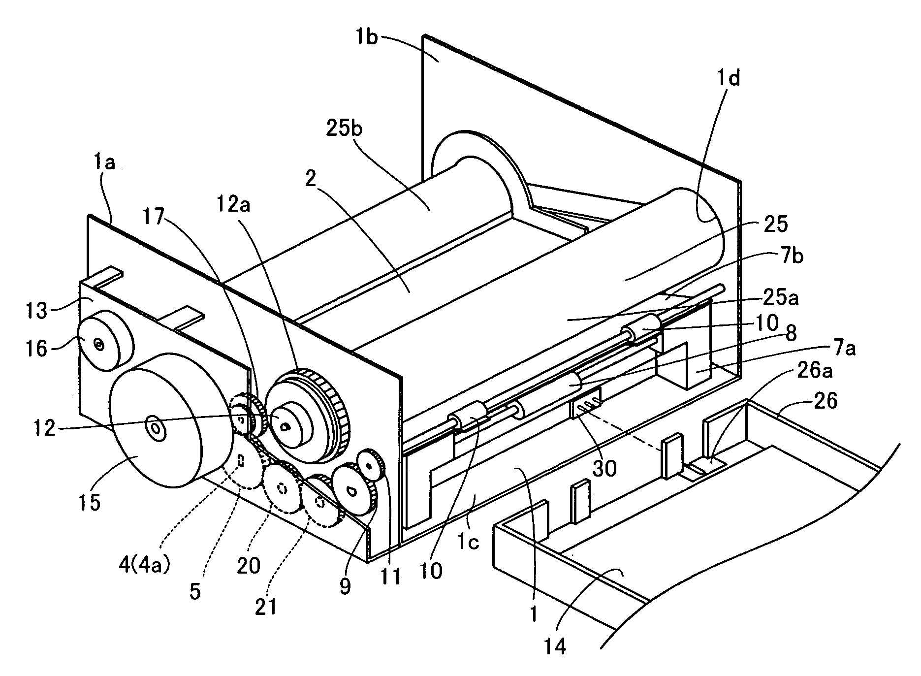
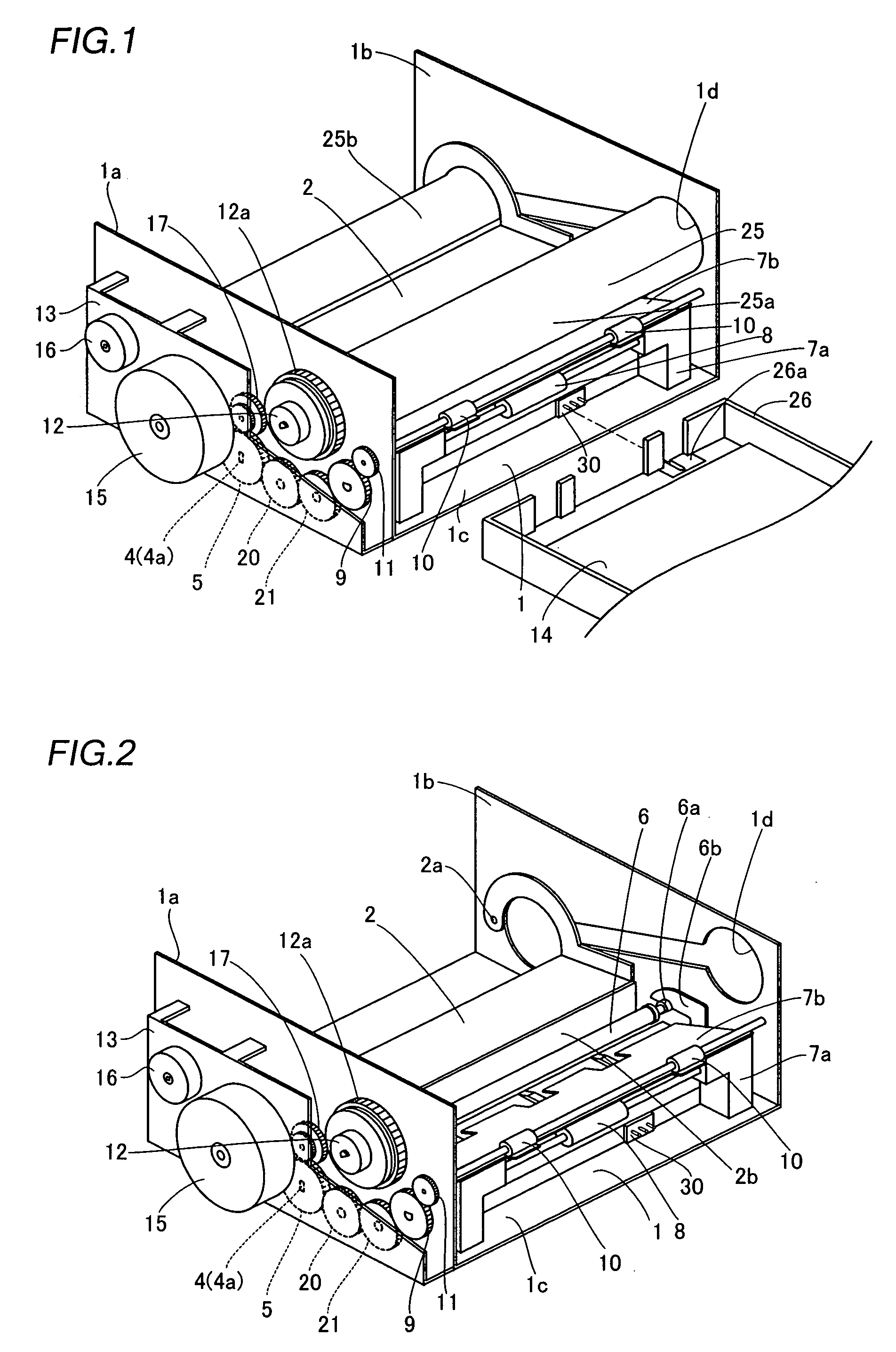
[0049] As shown in FIGS. 1 and 2, the thermal transfer printer according to this embodiment of the present invention comprises a chassis 1 of metal, a print head 2 for printing, a platen roller 3 (see FIG. 12) opposed to the print head 2, a feed roller 4 (see FIG. 12) of metal, a feed roller gear 5, a press roller 6 (see FIG. 12) of metal pressing the feed roller 4 with prescribed pressing force, a lower paper guide 7a of resin, an upper paper guide 7b of resin, a paper feed roller 8 of rubber, a paper feed roller gear 9, a paper discharge roller 10 of rubber, a paper discharge roller gear 11, a take-up reel 12...


PUM


Abstract

A printer capable of reducing a time for increasing the temperature of a heating element to a proper level for starting printing beforehand and suppressing density reduction in an initial stage of printing is obtained. This printer comprises a print head having a heating element for printing an image on a paper, a platen roller against which the print head is pressed through an ink sheet and the paper and print head control means applying a prescribed voltage to the heating element of the print head while carrying the paper after pressing the print head against the platen roller and before starting printing.

Description

BACKGROUND OF THE INVENTION [0001] 1. Field of the Invention [0002] The present invention relates to a printer, and more particularly, it relates to a printer comprising a print head. [0003] 2. Description of the Background Art [0004] In relation to a printer such as a thermal transfer printer, various structures are generally proposed in order to suppress reduction of print density by applying a voltage pulse (dummy pulse) to a heating element of a thermal head (print head) while performing printing on a print area. For example, Japanese Patent Laying-Open Nos. 56-161182 (1981) and 9-216398 (1997) propose such structures. [0005] The aforementioned Japanese Patent Laying-Open No. 56-161182 describes a printer capable of suppressing reduction of print density by inhibiting the temperature of a heating element of a thermal head (print head) from decreasing below a proper level by applying a dummy pulse (voltage pulse) of an energy level causing no reaction of a thermal recording mediu...

Claims


Application Information

Patent Timeline
IPC IPC(8): B41J2/32
CPCB41J2/36B41J2/38B41J2/375
Inventor NAITO, TADAHIRO
Owner FUNAI ELECTRIC CO LTD
Why Eureka
Try Eureka