Unlock instant, AI-driven research and patent intelligence for your innovation.

Continuous process and apparatus for the production of engineered catalyst materials

a technology of nanoscale catalyst and process equipment, which is applied in the direction of catalyst activation/preparation, physical/chemical process catalyst, coating, etc., can solve the problems of not allowing a great deal of precision, the amount of time it takes to load on a carrier particle, and the application of catalyst materials

Inactive Publication Date: 2007-02-15
DIRECTA PLUS
View PDF11 Cites 4 Cited by
  • Summary
  • Abstract
  • Description
  • Claims
  • Application Information

AI Technical Summary

Benefits of technology

[0023] The reactor vessel can be formed of any material which can withstand the conditions under which the decomposition of the moiety occurs. Generally, where the reactor vessel is a closed system, that is, where it is not an open ended vessel permitting reactants to flow into and out of the vessel, the vessel can be under subatmospheric pressure, by which is meant pressures as low as about 250 millimeters (mm). Indeed, the use of subatmospheric pressures, as low as about 1 mm of pressure, can accelerate decomposition of the decomposable moiety and provide smaller nano-scale particles. However, one advantage of the inventive process is the ability to produce nano-scale particles at generally atmospheric pressure, i.e., about 760 mm. Alternatively, there may be advantage in cycling the pressure, such as from sub-atmospheric to generally atmospheric or above, to encourage nano-deposits within the structure of the support. Of course, even in a so-called “closed system,” there needs to be a valve or like system for relieving pressure build-up caused, for instance, by the generation of carbon monoxide (CO) from the carbonyl decomposition or other by-products. Accordingly, the use of the expression “closed system” is meant to distinguish the system from a flow-through type of system as discussed hereinbelow.
[0048] It is yet another object of the present invention to provide an apparatus which permits the continuous production of engineered nano-scale catalyst particles in a continuous process.

Problems solved by technology

One major drawback to the preparation of catalyst materials through loading on a carrier particle is in the amount of time the loading reactions take, which can be measured in hours in some cases.
An additional drawback to the use of conventional carrier-particle loaded catalysts lies in the fact that the typical method of applying these materials to the support on which they are to be employed is by forming a suspension of the particles in a fluoroelastomer and then painting the admixed fluid onto the support, after which the suspension is “baked” to bond the content to the support, leaving a coating of the catalyst coated carrier particles on the surface of the support.
This method does not allow for a great deal of precision, resulting in the application of catalyst material at locations where it is not needed or desired.
Given the cost of catalyst materials, especially the noble metal materials typically considered most efficacious, this “painting” method of application of catalysts is extremely disadvantageous.
Thus, these processes are difficult and expensive to operate.
Even if technically feasible, however, the Bert and Bianchini methods require high temperatures (on the order of 300° C. to 800° C.)
, and require several hours. A
ccordingly, these processes are of limited value.
One major drawback to the traditional “solution” or resin based methods of producing catalyst materials lies in the precision (or, more specifically, the lack thereof) with which the catalyst particles are produced, especially when a hereto catalyst (i.e., one containing more than one metallic specie) having a specific constitution (for instance, ratio or orientation of metallic species in the particle) is desired.
The situation is somewhat better in the chemical sputtering and other direct deposition processes, however, the difficulty is that these are typically line of sight methods and cost of these processes is prohibitive.
Because of these drawbacks, it is difficult, if not impossible, to tailor (or engineer) a catalyst particle for a specific reaction.

Method used


Image

  • Continuous process and apparatus for the production of engineered catalyst materials
  • Continuous process and apparatus for the production of engineered catalyst materials
  • Continuous process and apparatus for the production of engineered catalyst materials

Examples


Embodiment Construction

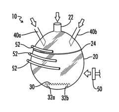
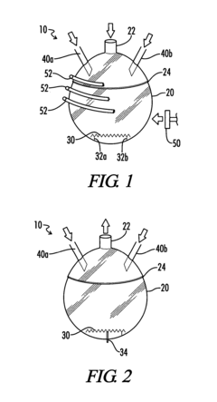
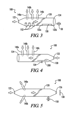
[0058] Referring now to the drawings, an apparatus in which the inventive process for the production of engineered nano-scale catalyst particles can be practiced is generally designated by the numeral 10 or 100. In FIGS. 1 and 2 apparatus 10 is a closed system comprising closed reactor vessel 20 whereas in FIGS. 3-5 apparatus 100 is a flow-through reaction apparatus comprising flow-through reactor vessel 120.

[0059] It will be noted that FIGS. 1-5 show apparatus 10, 100 in a certain orientation. However, it will be recognized that other orientations are equally applicable for apparatus 10, 100. For instance, when under vacuum, reactor vessel 20 can be in any orientation for effectiveness. Likewise, in flow-through reactor vessel 120, the flow of inert carrier gas and decomposable moieties or the flow of decomposable moieties as drawn by a vacuum in FIGS. 3-5 can be in any particular direction or orientation and still be effective. In addition, the terms “up”“down”“right” and “left” ...


PUM

PropertyMeasurementUnit
Temperatureaaaaaaaaaa
Lengthaaaaaaaaaa
Lengthaaaaaaaaaa

Abstract

A process and apparatus for continuously producing nano-scale catalyst particles includes continuously feeding at least one decomposable moiety selected from the group consisting of organometallic compounds, metal complexes, metal coordination compounds and mixtures thereof into a reactor vessel, wherein the nature of the decomposable moiety introduced into the reactor vessel through each feeder, the rate of feeding of each decomposable moiety, or the order in which different species are fed into the reactor vessel is controlled; exposing the decomposable moiety to a source of energy sufficient to decompose the moiety and produce nano-scale metal particles; and depositing the nano-scale catalyst particles on a support or in a collector.

Description

TECHNICAL FIELD [0001] The present invention relates to a continuous process and apparatus for the production of engineered nano-scale catalyst metal particles. By the practice of the present invention, nano-scale catalyst particles can be produced with greater precision, speed and flexibility than can be accomplished with conventional processing, and the particles produced can be directly affixed to support materials in a precise and cost-effective manner. BACKGROUND OF THE INVENTION [0002] Catalysts are becoming ubiquitous in modern chemical processing. Catalysts are used in the production of materials such as fuels, lubricants, refrigerants, polymers, drugs, etc., as well as playing a role in water and air pollution mediation processes. Indeed, catalysts have been ascribed as having a role in fully one third of the material gross national product of the United States, as discussed by Alexis T. Bell in “The Impact of Nanoscience on Heterogeneous Catalysis” (Science, Vol. 299, pg. ...

Claims


Application Information

Patent Timeline
IPC IPC(8): B05D1/12B05D3/00
CPCB01J35/0013B82Y30/00B01J37/086B01J35/23
Inventor MERCURI, ROBERT A.
Owner DIRECTA PLUS