Magnetic navigation and imaging system

a navigation and imaging system technology, applied in the field of magnetic surgery system, can solve the problems of less accessibility of the operating region of the patient, difficult and time-consuming for the physician, and the only surgeon with the most skilled skills, so as to improve flexibility and accessibility.

Inactive Publication Date: 2007-02-15
STEREOTAXIS
View PDF97 Cites 76 Cited by
  • Summary
  • Abstract
  • Description
  • Claims
  • Application Information

AI Technical Summary

Benefits of technology

[0007] Embodiments of the systems of the present invention advance the art of simultaneous imaging and remote surgical navigation by combining navigation and imaging system equipment in a manner that improves flexibility and accessibility of both systems. In one embodiment of the present invention, a system for imaging and magnetically navigating a medical device within an operating region in a subject's body is provided that comprises a first C-arm and a second C-arm. The system comprises an imaging beam source and an imaging beam receiver mounted on the first C-arm and positioned to be disposed on opposite sides of the operating region to image the operating region. The system further comprises an imaging beam source and an imaging beam receiver mounted on the second C-arm and positionable to be disposed on opposite sides of the operating region to image the operating region. In this embodiment, the second C-arm is movable between an imaging position in which the imaging beam source and imaging beam receiver on the second C-arm is positioned so that the imaging beam sources and receivers are in the same plane, and a stowed position in which the second C-arm is in a navigating position. The system comprises a pair of magnetic pods movably mounted on the first C-arm, the magnetic pods being movable between a navigating position in which the pods are disposed on opposite sides of the operating region in the same plane as the imaging beam source and the imaging beam receiver, for applying a navigating magnetic field of at least 0.08 T in any direction to the operating region, and a stowed position in which the magnets are moved out of the plane to accommodate the imaging beam source and imaging beam receiver on the second C-arm in its imaging position. The imaging beam source and the imaging beam receiver on the first C-arm are positioned so that a line between the imaging beam source and receive is generally perpendicular to, and coplanar with a line between the magnet pods in their navigating position.
[0008] In another aspect of the present invention, a second embodiment of a system provides for quickly moving between a position for navigation operation and a position for imaging. In the second embodiment, the system comprises a first C-arm, and a second C-arm having an imaging beam source and beam receiver mounted generally adjacent the magnet pods, such that the second C-arm may move from a navigation position utilizing the magnet pods to an imaging position utilizing the imaging beam source and beam receiver. The system comprises an imaging beam source and an imaging beam receiver mounted on the first C-arm so that the imaging beam source and imaging beam receiver can be disposed on opposite sides of the operating region in the subject. The system also comprises a second C-arm movable relative to the first C-arm between a stowed position and an imaging position, and having an imaging beam source and an imaging beam receiver mounted on the second C-arm. When the second C-arm is in its imaging position, the imaging beam source and imaging beam receiver are disposed on opposite sides of the operating region, in substantially the same plane as the imaging beam source and imaging beam receiver on the first C-arm. The second C-arm comprises a pair of magnetic pods mounted on the first C-arm, the C-arm being movable between a navigating position in which the pods are disposed on opposite sides of the operating region in the same plane as the imaging beam source and the imaging beam receiver, for applying a navigating magnetic field of at least 0.08 T in any direction to the operating region, and a stowed position in which the magnets are not on opposite sides of the operating region to accommodate the imaging beam source and imaging beam receiver on the second C-arm in its imaging position. When in the stowed position, the imaging beam source and the imaging beam receiver on the second C-arm are positioned so that a line between the imaging beam source and receiver is generally perpendicular to, and coplanar with a line between the magnet pods in their navigating position.

Problems solved by technology

While these procedures are highly beneficial to the patient, they are difficult and time consuming for the physician.
Some procedures can only be performed by the most skilled surgeons.
While magnetically guided surgery with such systems is practical, the sheer bulk and size of their magnetic systems results in less accessibility of the operating region of the patient than a surgeon might prefer.
This relative immobility tends to reduce the ability of the surgeons to see the medical operating device within the patient, making the operation somewhat more difficult for the surgeon and somewhat riskier for the patient than might otherwise be the case.

Method used


Image

  • Magnetic navigation and imaging system
  • Magnetic navigation and imaging system
  • Magnetic navigation and imaging system

Examples


first embodiment

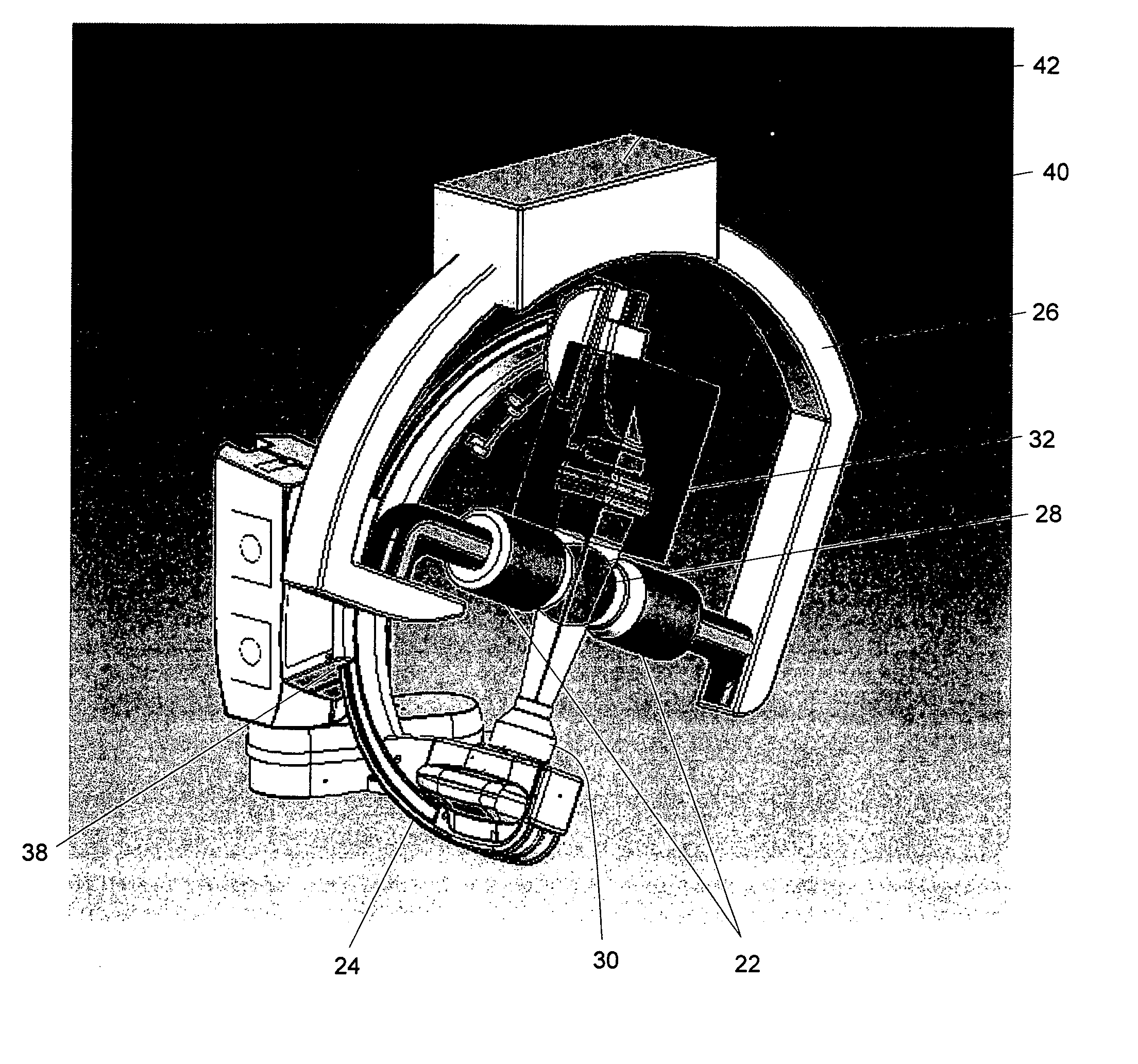
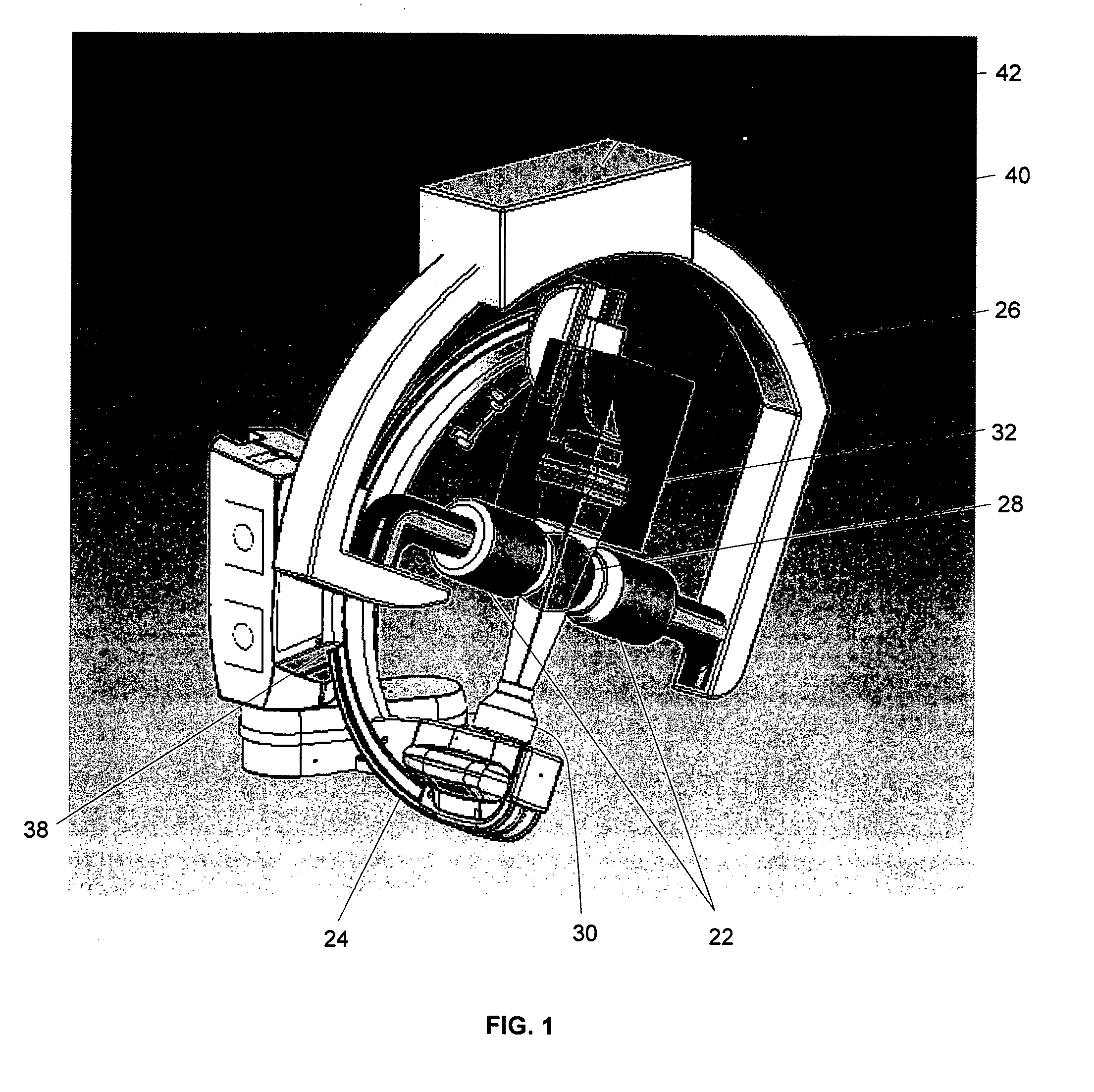
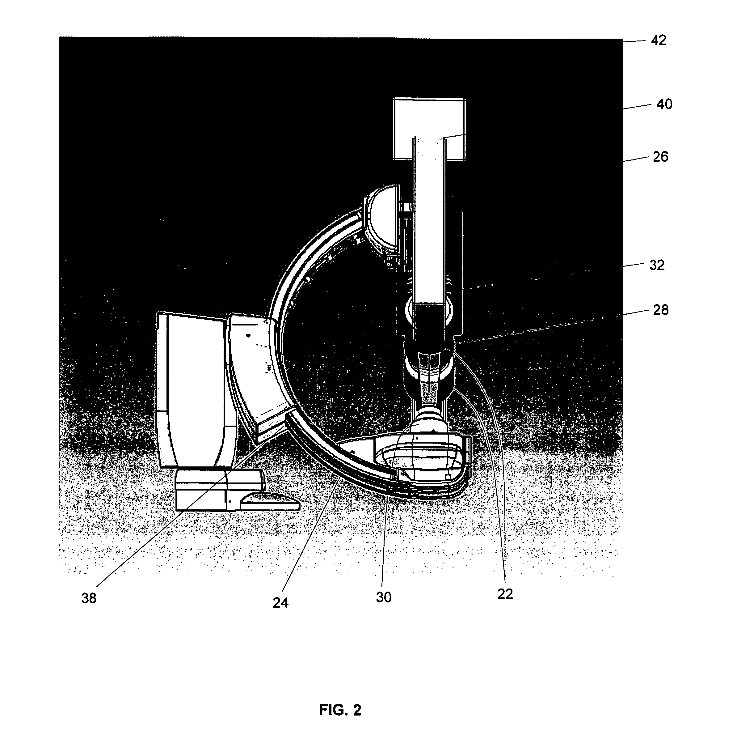
[0031] In one first embodiment of the present invention, a system that enables both imaging and magnetic navigation within an operating region of a subject's body is provided. The system comprises magnetic navigational equipment 22 that provides navigation control in an operating region 28 of a subject's body, as well as imaging equipment for procedures where anatomical views of the patient may be required during the procedure. The system generally comprises a first imaging equipment support structure having a generally C-shaped configuration 24, and a second equipment support structure having a generally C-shaped configuration 26. The first and second C-arm structures are preferably mounted on tracks that enable the C-arms to rotate circumferentially about an operating region 28 of the subject's body as shown in FIG. 1.

[0032] In the first embodiment, the system comprises a first C-arm 24 with an imaging beam source 30 and an imaging beam receiver 32 that are mounted on the first C-...

second embodiment

[0035] Referring to FIGS. 3-11, a system is provided that enables both primary and secondary imaging as well as magnetic navigational control within a subject's body. The system comprises magnetic navigational equipment 22 that may be moved from a first navigational position to a second position for enabling secondary imaging equipment to have access to the operating region of the subject's body, for example, during a procedure where additional views of the patient are required for the procedure. The system generally comprises a first imaging equipment support structure 24 having a generally C-shaped configuration, and a second imaging equipment support structure 26 having a generally C-shaped configuration. The first and second C-arm structures 24 and 26 are preferably mounted on tracks 38 and 40 that enable the first and second C-arms 24 and 26 to rotate in a generally circumferential arc about an operating region 28 of the subject's body as shown in FIG. 3.

[0036] In the second em...

third embodiment

[0045] The third embodiment further comprises a second C-arm 26 that is mounted on a track support 40 for enabling the second C-arm to rotate about the radial center of the second C-arm 24. The second C-arm 24 rotates in a generally circumferential arc about the operating region 28. The track support 40 is preferably mounted via a motorized trolley or travel mechanism to an overhead linear track 42 that is parallel to the longitudinal axis of the patient and / or support table 44. The overhead linear track 42 enables the second C-arm 26 to be moved to a secondary imaging position, such that a line between the imaging beam source 30 and receive 32 on the first C-arm 24 is generally perpendicular to, and coplanar with a line between the imaging beam source 34 and imaging beam receiver 36 on the second C-arm 26. The second C-arm 26 shown in FIG. 12 is preferably an overhead secondary Siemens C-arm, but may alternatively be any equivalent system capable of rotation about an operating regi...


PUM


Abstract

A system for imaging and magnetically navigating a medical device within an operating region in a subject's body is provided that comprises a first C-arm and a second C-arm. The system comprises an imaging beam source and an imaging beam receiver mounted on the first C-arm that are positioned to be disposed on opposite sides of the operating region to image the operating region. Some embodiments comprise a pair of magnetic pods, which are movably mounted on either the first or second C-arm. Some embodiments comprise magnetic pods that are movable between an imaging position and a navigating position in which the pods are disposed on opposite sides of the operating region in the same plane as at least one imaging beam source. The magnetic navigation units may apply a navigating magnetic field of at least 0.08 T in any direction to the operating region. In some embodiments of the invention, the second C-arm is movable between an imaging position in which the imaging beam source and imaging beam receiver on the second C-arm is positioned so that the imaging beam sources and receivers are in the same plane.

Description

CROSS-REFERENCE TO RELATED APPLICATIONS [0001] This application claims the benefit of U.S. Provisional Patent Application Ser. No. 60 / 697,822 filed on Jul. 8, 2005, the entire disclosure of which are incorporated herein by reference.FIELD OF THE INVENTION [0002] This invention relates to a magnetic surgery system, and in particular to an open magnetic surgery system that provides greater access to the patient for imaging and other purposes. BACKGROUND OF THE INVENTION [0003] A wide variety of minimally invasive surgical procedures have been developed which employ catheters, endoscopes, or other similar devices that can be navigated remotely from their distal ends. The catheter, endoscope or other medical device is manipulated through the tissue or through an existing body lumen or cavity using a guide wire or other mechanical means. Examples of such procedures include the treatment of aneurysms, arterial ventricular malformations, atrial fibrillation, ureteral stones, and investigat...

Claims


Application Information

Patent Timeline
Patent Type & Authority Applications(United States)
IPC IPC(8): A61B5/05
CPCA61B5/06A61B6/12A61B2019/5238A61B2019/2253A61B2019/2261A61B19/22A61B34/70A61B34/73A61B2034/732A61B2090/376
Inventor CREIGHTON, FRANCIS M. IV
Owner STEREOTAXIS
Why Eureka
Try Eureka