
Connector strip for partition panel assembly

Inactive Publication Date: 2007-02-22
STEELCASE INC
View PDF22 Cites 9 Cited by
  • Summary
  • Abstract
  • Description
  • Claims
  • Application Information

AI Technical Summary

Benefits of technology

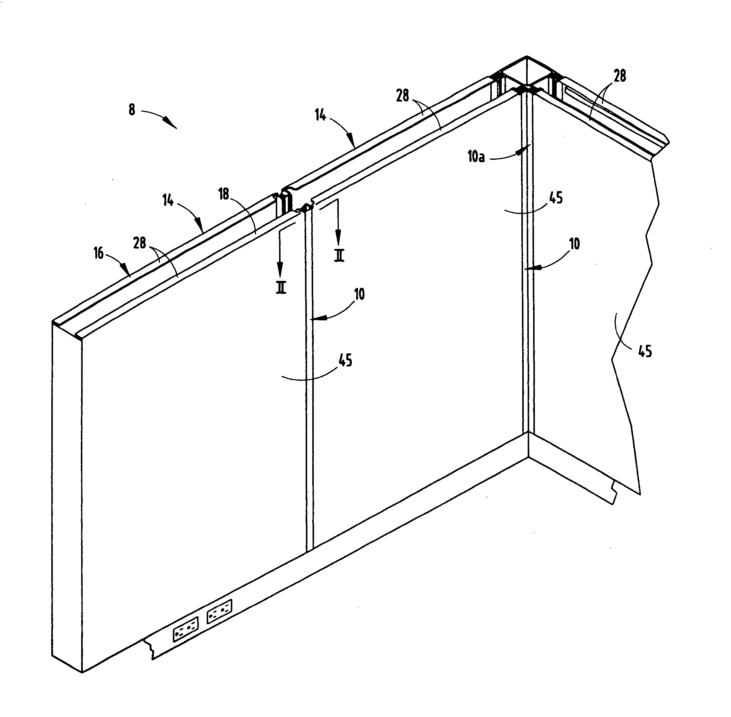
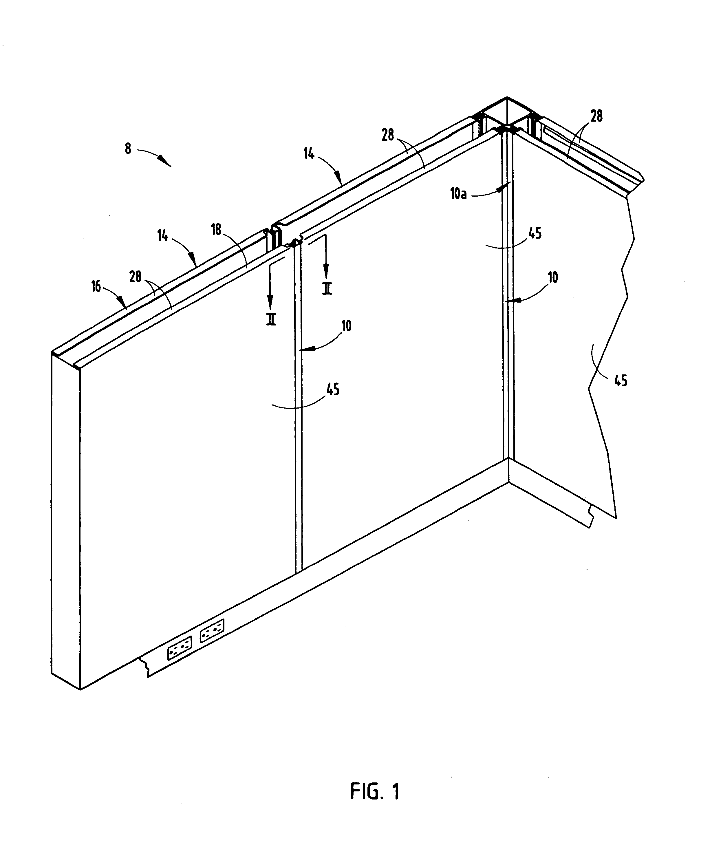
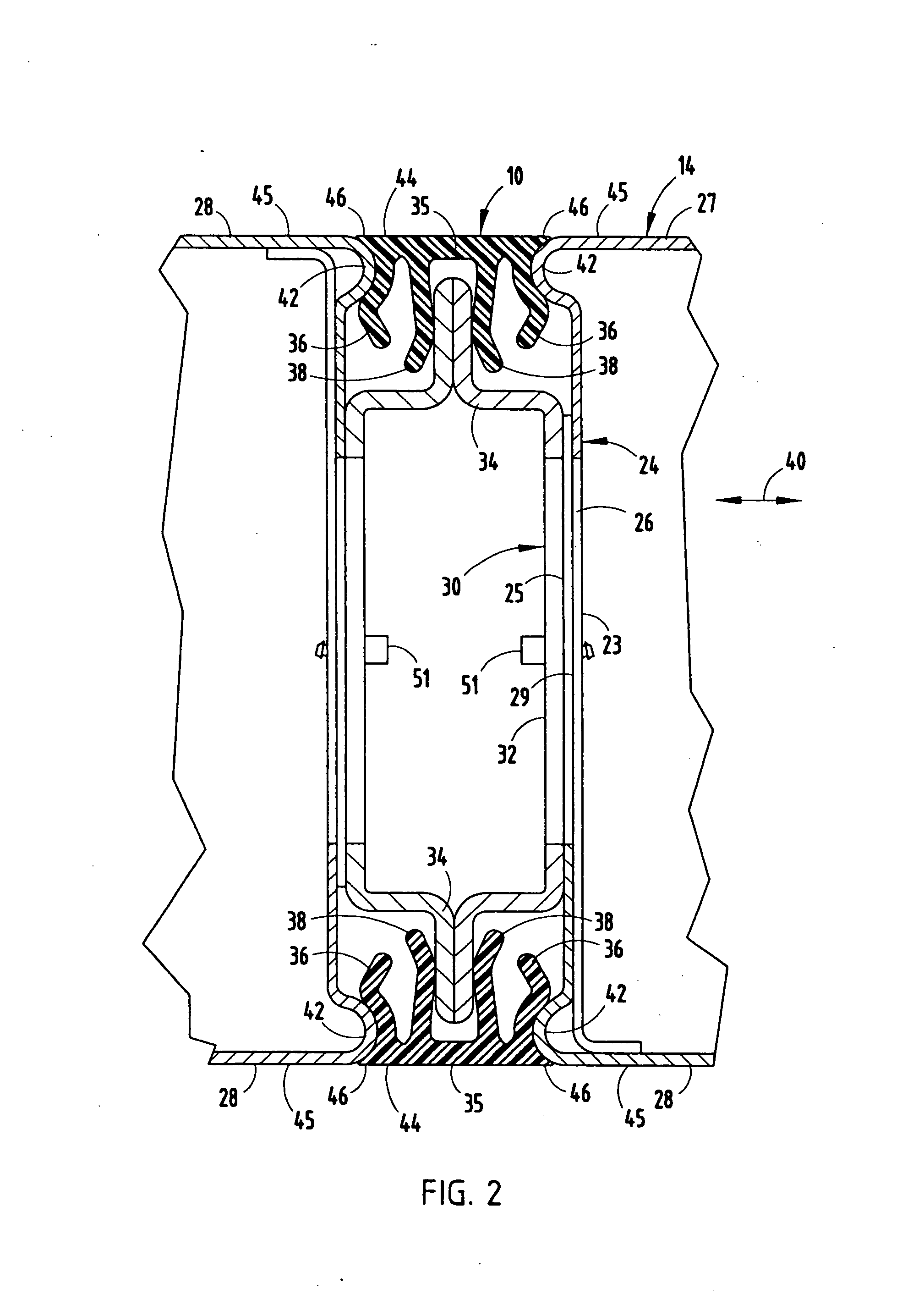
[0007] The construction of a plastic vinyl connector strip that has an exterior face that is substantially flush with the sides of a partition panel creates a continuous and aesthetically pleasing appearance. Furthermore, the connector strip is coated or painted to conform aesthetically with the color of the partition panels thereby increasing the aesthetic quality of the partition panel assembly. Still further, the connector strip couples adjacent panels together eliminating additional mechanical couplers typically required, while simultaneously increasing the connector strip increases the connection strength between panels thereby decreasing the likelihood that the panels will become unattached. Moreover, the strip serves as an acoustical barrier between adjacent panels.

Problems solved by technology

Heretofore, these covers are typically thick in nature and do not create a visually subtle transition from one panel to the next.
Moreover, the fasteners coupling the partition panels together are complicated and relatively expensive as they are constructed separately from the cover members.

Method used


Image

  • Connector strip for partition panel assembly
  • Connector strip for partition panel assembly
  • Connector strip for partition panel assembly

Examples


Embodiment Construction

[0015] For purposes of description herein the terms “upper”, “lower”, “right”, “left”, “rear”, “front”, “vertical”, “horizontal” and derivatives thereof shall relate to the invention as oriented in FIGS. 1 and 2. However, it is to be understood that the invention may assume various alternative orientations and step sequences, except where expressly specified to the contrary. It is also to be understood that the specific devices and processes illustrated in the attached drawings, and described in the following specification are exemplary embodiments of the inventive concepts defined in the appended claims. Hence, specific dimensions and other physical characteristics relating to the embodiments disclosed herein are not to be considered as limiting, unless the claims expressly state otherwise.

[0016] The reference numeral 8 (FIG. 1) generally designates a partition panel assembly embodying the present invention and that is adapted to divide work spaces in an office setting. The partit...


PUM


Abstract

A partition panel assembly comprises first and second partition panels each having a first outer surface, an end surface, and a first flange extending outwardly from the end surface. The partition panel assembly also comprises an elongate connector strip including a body portion having an outer surface, first and second inner legs extending from the body portion, wherein the first and second inner legs couple the first flange of the first and second partition panels together, and first and second outer legs extending from the body portion of the connector strip that abut the end surfaces of the first and second partition panels, such that the outer surface of the connector strip is substantially planar with the outer surface of each of the first and second partition panels.

Description

BACKGROUND OF THE PRESENT INVENTION [0001] The present invention relates to a connector strip for a partition panel assembly, and in particular to a connector strip operably coupling a pair of adjacent partition panels and providing an aesthetic covering therebetween to create the look of a single, uninterrupted panel. [0002] Partition assemblies are generally comprised of multiple partition panels arrangeable to separate work stations in an office setting. These partition panels will frequently be of a reasonably maneuverable length, width and height and adapted to be connected to one another at the ends thereof. Each end of a given partition panel typically has a connection point capable of connecting with another partition via a mechanical-type fastener such as interlocking brackets, screws, bolts and the like. Covers extending between the coupled partition panels may be used to assist in connecting the partition panels as well as to hide the mechanical fasteners connecting the p...

Claims


Application Information

Patent Timeline
IPC IPC(8): E04H1/00
CPCE04B2002/7446E04B2/7425
Inventor MACDONALD, DOUGLAS B.PALERMO, WILLIAM H.
Owner STEELCASE INC
Learn More