Stepping motor

Active Publication Date: 2011-06-16
MINEBEAMITSUMI INC
View PDF4 Cites 32 Cited by
  • Summary
  • Abstract
  • Description
  • Claims
  • Application Information

AI Technical Summary

Benefits of technology

[0011]The present invention has been made to solve the problem described above, and it is an aspect of the present invention to provide a stepping motor in which an assembling operation is simplified by using a band without caulking in order to fix a front plate to a stator, the front plate is prevented from being deformed to obtain stable motor characteristics having less non-uniformity, and the band is prevented from being rotated to increase a connection strength between the stator and the front plate.
[0014]According to the above configuration, it is possible to provide a stepping motor in which since the front plate is not fixed by caulking, an assembling operation is simplified, the front plate is prevented from being deformed to obtain stable motor characteristics having less non-uniformity, and the band is prevented from being rotated to increase a connection strength between the stator and the front plate.

Problems solved by technology

However, this fixing operation of the attachment plate 104 by caulking is not easy.
As a result, the rotor 103 cannot be smoothly rotated, thereby causing vibration and noise of the motor.
Further, non-uniformity in properties of the motor may be caused.
Thus, it is difficult to realize reducing the size.

Method used


Image

  • Stepping motor
  • Stepping motor
  • Stepping motor

Examples


Embodiment Construction

First Illustrative Embodiment

[0027]Hereinafter, a first illustrative embodiment of the present invention will be described with reference to FIG. 1 to FIG. 5.

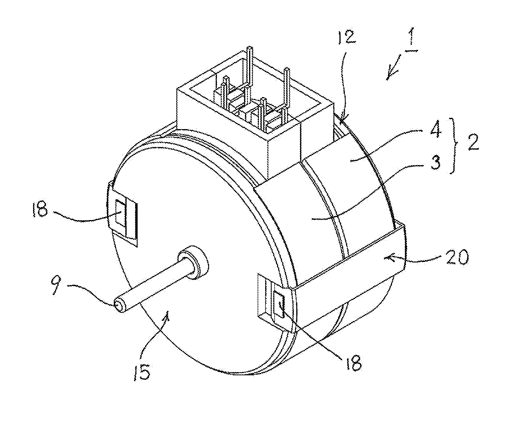
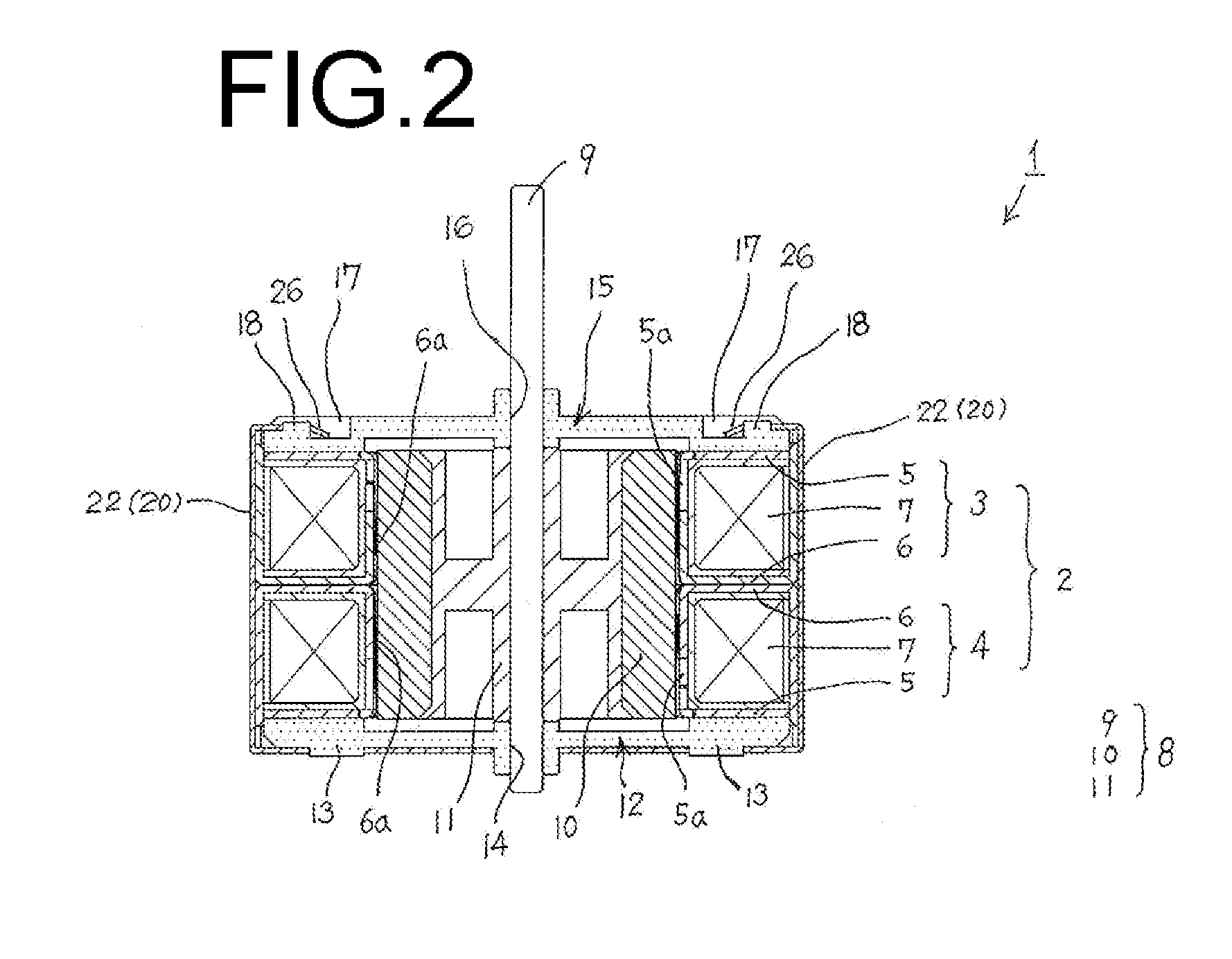
[0028]FIG. 1 is a perspective view of a stepping motor according to the first illustrative embodiment of the present invention. The stepping motor includes a stator and a front plate connected by a band, FIG. 2 is a sectional view of the stepping motor shown in FIG. 1, FIG. 3 is an exploded perspective view of the stepping motor shown in FIG. 1, and FIG. 4 shows a bottom surface of the stepping motor shown in FIG. 1.

[0029]A stepping motor 1 according to a first illustrative embodiment includes a stator 2 and a rotor 8. The stator 2 has a stator unit 3 (A phase) and a stator unit 4 (B phase) and the stator unit 3 (A phase) and the stator unit 4 (B phase) are stacked in an axial direction to form a two-phase structure. The rotor 8 has a shaft 9, a rotor magnet 10 and a sleeve 11. The rotor magnet 10 is fixed to an outer circumfer...


PUM


Abstract

A motor includes a stator having boss portions on an end plate thereof, a front plate provided on an upper surface of the stator, and a band connecting the stator and the front plate. Recess portions are formed adjacent to an outer peripheral edge of the front plate, and a protruding portion is provided in each recess portion. The band has a bottom plate part and attachment parts. The bottom plate part includes notched portions. Each attachment part includes an engagement portion at a tip end thereof which includes a notched portion. The notched portions of the bottom plate part are fitted with the boss portions of the end plate, and the notched portions of the engagement portions are fitted with the protruding portions of the front plate to form engagement hooks at most tip ends of the engagement portions, respectively, thereby connecting the stator and the front plate.

Description

BACKGROUND OF THE INVENTION[0001]1. Field of the Invention[0002]The present invention relates to a stepping motor, and particularly, to a connection structure of a stator yoke and a front plate.[0003]2. Description of the Related Art[0004]In a related-art stepping motor, as shown in FIG. 9, an attachment plate 104 which rotationally supports a rotor 103 is caulking-fixed to a motor frame 102 which holds a stator 101. Specifically, a caulking piece 106 is engaged to a caulking recess portion 105 formed by cutting at an open edge portion of the motor frame 102, and the caulking piece 106 is then caulked to fix the attachment plate 104.[0005]However, this fixing operation of the attachment plate 104 by caulking is not easy. In addition, the caulking fixing of the attachment plate 104 causes deformation or distortion in the attachment plate 104, which in turn causes a core deviation between the rotor 103 and a bearing 107 mounted to the attachment plate 104. As a result, the rotor 103 c...

Claims


Application Information

Patent Timeline
IPC IPC(8): H02K5/04
CPCH02K5/15
Inventor KINPARA, SHUHEISUZUKI, YUZURUFUJIMOTO, SEIYA
Owner MINEBEAMITSUMI INC
Why Eureka
Try Eureka