
Mechanical assembly for securing sheets and related method

Active Publication Date: 2021-02-11
BRENTWOOD INDS
View PDF0 Cites 1 Cited by
  • Summary
  • Abstract
  • Description
  • Claims
  • Application Information

AI Technical Summary

Benefits of technology

The patent describes a mechanical assembly with an improved connection system that requires less force to make the connection and provides increased strength. This results in stronger and more reliable products made using the mechanical assembly. The connection system also reduces the variation in strength of the connection, resulting in more reliable and consistent product performance. The defect in the connection system also reduces the cost and complexity of the assembly equipment used to create the connection. Additionally, the patent suggests that different configurations of the defect can be used depending on the needs of the application, such as whether the sheets will be stored or assembled immediately. Overall, the patent presents a solution to create stronger, more reliable mechanical assemblies.

Problems solved by technology

The basic concept came from the fact that a soda can is able to support significant weight, such as the weight of a person, however, when the sides of the can are deformed by an outside influence, such as squeezing the sidewalls of the can inwardly with your fingers, the can suddenly collapses under the weight, such as the weight of the person.
Additionally, poor or inconsistent projection-depression coupling may necessitate post-manufacturing repair.
If the nested cones do not fail similarly, then the infinite variations in the final connection geometry of the prior art crushed cones or projections can cause a lack of connection of the sheets or failure during handling.
Homogeneous cones will not nest properly and cause a reduction in strength if assembled

Method used


Image

  • Mechanical assembly for securing sheets and related method
  • Mechanical assembly for securing sheets and related method
  • Mechanical assembly for securing sheets and related method

Examples


Embodiment Construction

[0031]Certain terminology is used in the following description for convenience only and is not limiting. Unless specifically set forth herein, the terms “a”, “an” and “the” are not limited to one element but instead should be read as meaning “at least one”. The words “right,”“left,”“lower,” and “upper” designate directions in the drawings to which reference is made. The words “inwardly” or “distally” and “outwardly” or “proximally” refer to directions toward and away from, respectively, the geometric center or orientation of the mechanical assembly, the sheets and related parts thereof. The terminology includes the above-listed words, derivatives thereof and words of similar import.

[0032]It should also be understood that the terms “about,”“approximately,”“generally,”“substantially” and like terms, used herein when referring to a dimension or characteristic of a component of the invention, indicate that the described dimension / characteristic is not a strict boundary or parameter and ...


PUM

PropertyMeasurementUnit
Angleaaaaaaaaaa
Shapeaaaaaaaaaa
Mechanical propertiesaaaaaaaaaa

Abstract

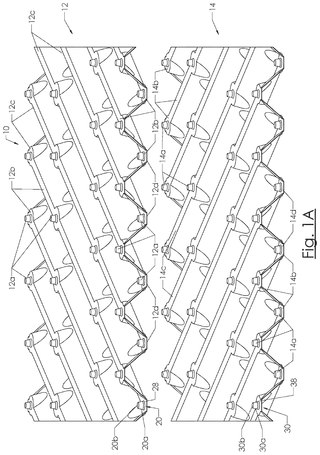
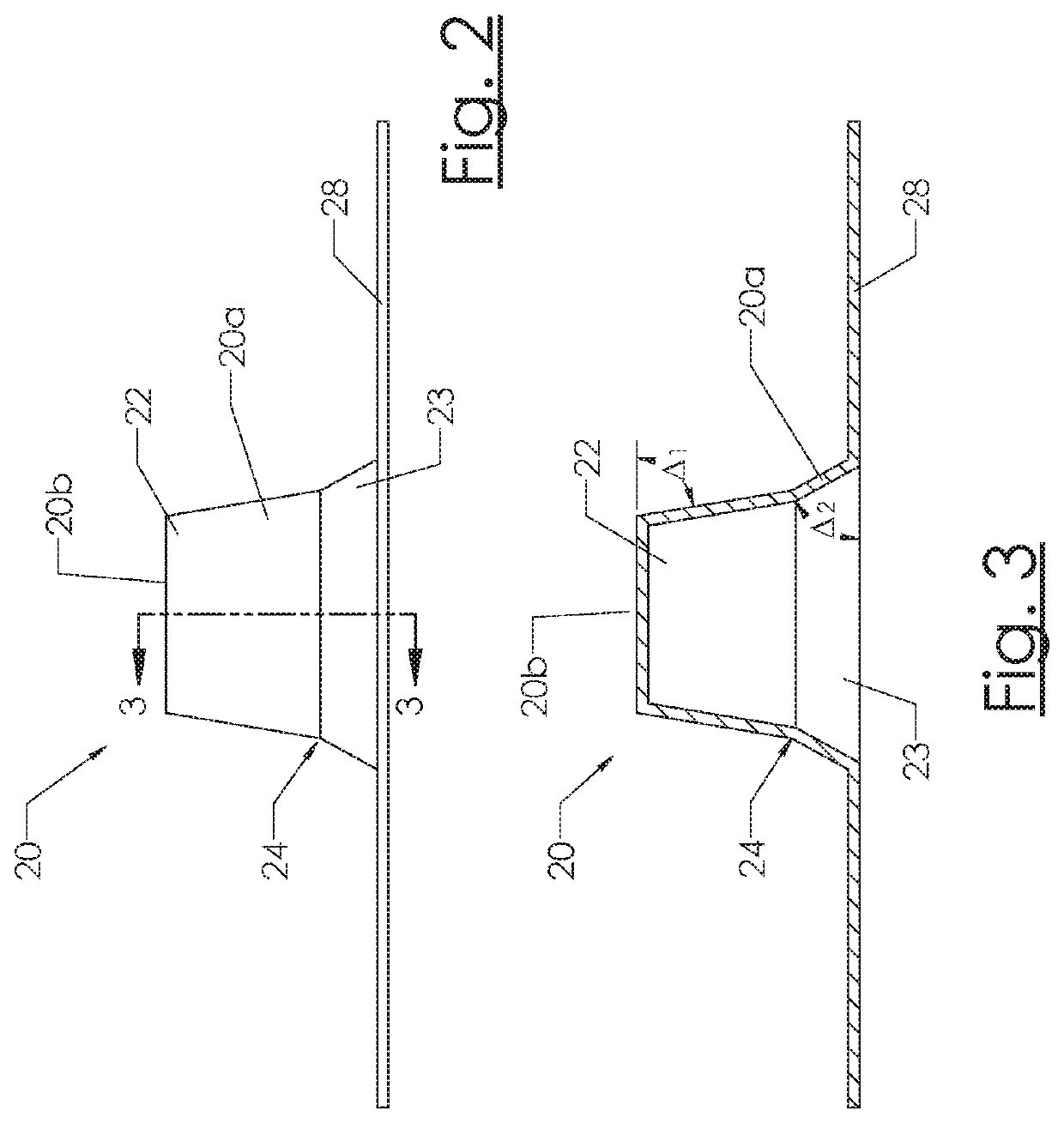
A mechanical assembly for securing a first sheet to a second sheet includes a first projection having a first sidewall and a first top wall. The first sidewall extends from the first top wall at a first acute angle. The first sidewall includes a first top end and a first bottom end. A first discontinuity is defined in the first sidewall between the first top end and the first bottom end. A first base wall extends from the first bottom end. The first base wall extends generally parallel to the first top wall.

Description

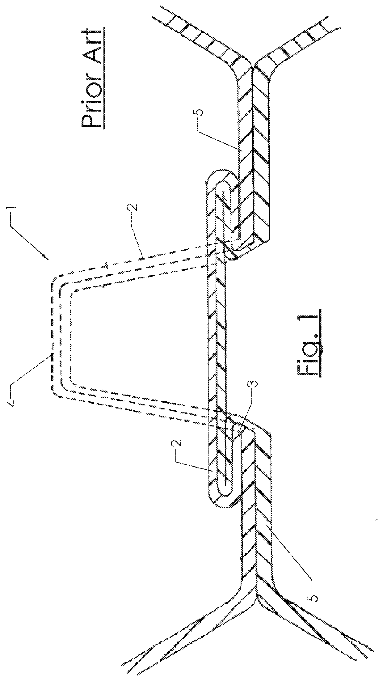
BACKGROUND OF THE INVENTION[0001]Mechanical assembly (MA) or positive locking refers generally to methods and structures for connecting structures with mechanical mechanisms. The MA described herein relates to mechanically connecting two polymeric sheets or films into pairs and pairs into packs or contact bodies, such as utilizing the mechanisms and methods for mechanically deforming materials into contact bodies or contact sheets described in U.S. Pat. No. 6,640,427 (“427 patent”), filed Oct. 24, 2002 and titled, “Apparatus for Making Contact Bodies;” U.S. Pat. No. 6,544,628 (“628 patent”), filed Sep. 13, 2000 and titled, “Contact Bodies and Method and Apparatus of Making Same” and U.S. Pat. No. 6,877,205 (“205 patent”), filed Oct. 24, 2002 and titled, “Method of Making Contact Bodies,” the contents of which are incorporated herein by reference in their entirety.[0002]Referring to FIG. 1, the shape of the prior art MA feature or truncated cones 1 of the '427 patent is a symmetric t...

Claims


Application Information

Patent Timeline
IPC IPC(8): F16B5/00B21D39/03
CPCF16B5/0096B21D39/031B29C65/56B29C66/73921B29C66/721B29C66/71B29C66/21B29C66/438B29C65/607B29L2031/18B29L2024/00F28F25/087B01J19/32B01J2219/3221B01J2219/32251B01J2219/32248B01J2219/32255B01J2219/328B01J2219/32408B01J2219/32416B01J2219/32483B29K2027/06B29K2025/06B29K2059/00B29K2077/00B29K2055/02B29K2025/08B29K2071/12B29K2081/06B29K2023/06B29K2023/12B29K2067/00B29K2083/00B29K2081/04B29K2063/00B29K2027/00B32B3/28B32B3/30B32B3/06
Inventor KULICK, III, FRANK M.EDWARDS, BRIANLINGLE, LUKE
Owner BRENTWOOD INDS
Learn More