Microfluidic flow monitoring device

a microfluidic flow and monitoring device technology, applied in laboratory equipment, electrolysis components, biochemistry instruments, etc., can solve the problems of increasing cost, cumbersome approaches, and difficulty in real sample handling

Inactive Publication Date: 2007-02-22
DIAGNOSWISS
View PDF12 Cites 35 Cited by
  • Summary
  • Abstract
  • Description
  • Claims
  • Application Information

AI Technical Summary

Problems solved by technology

However, these systems necessitate a perfect control of the wall surface during the analyses, which is difficult in real sample handling.
These approaches can be cumbersome when integrated into disposable microfluidic systems, notably because they increase the cost of the final sensor device.
In addition, the connection of a disposable part to an external capillary may become difficult to achieve without any contamination or dead volume.
The use of such pressure to generate a flow has seldom been applied to microfluidics because of the difficulty of efficiently monitoring the flow rate inside the chip while applying the pressure difference between the two covered microchannel ends.
Indeed, the volume present in the microchannel is so small that it is difficult not only to monitor the flow rate but even to be sure that the sample has entered the channel.

Method used


Image

  • Microfluidic flow monitoring device
  • Microfluidic flow monitoring device
  • Microfluidic flow monitoring device

Examples


Embodiment Construction

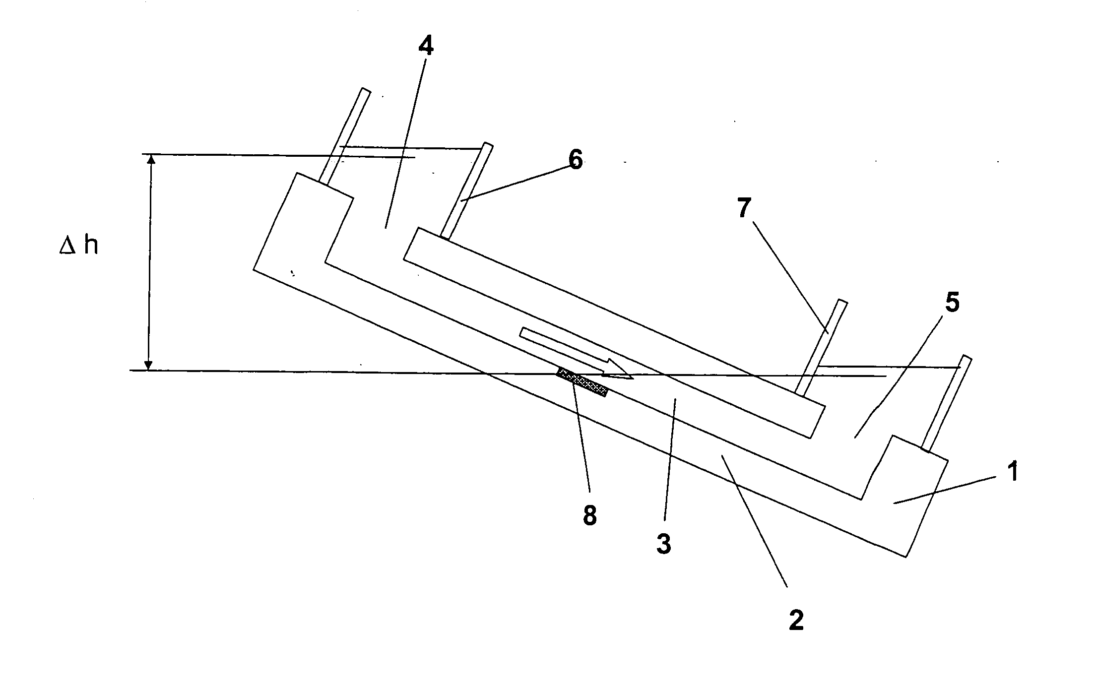
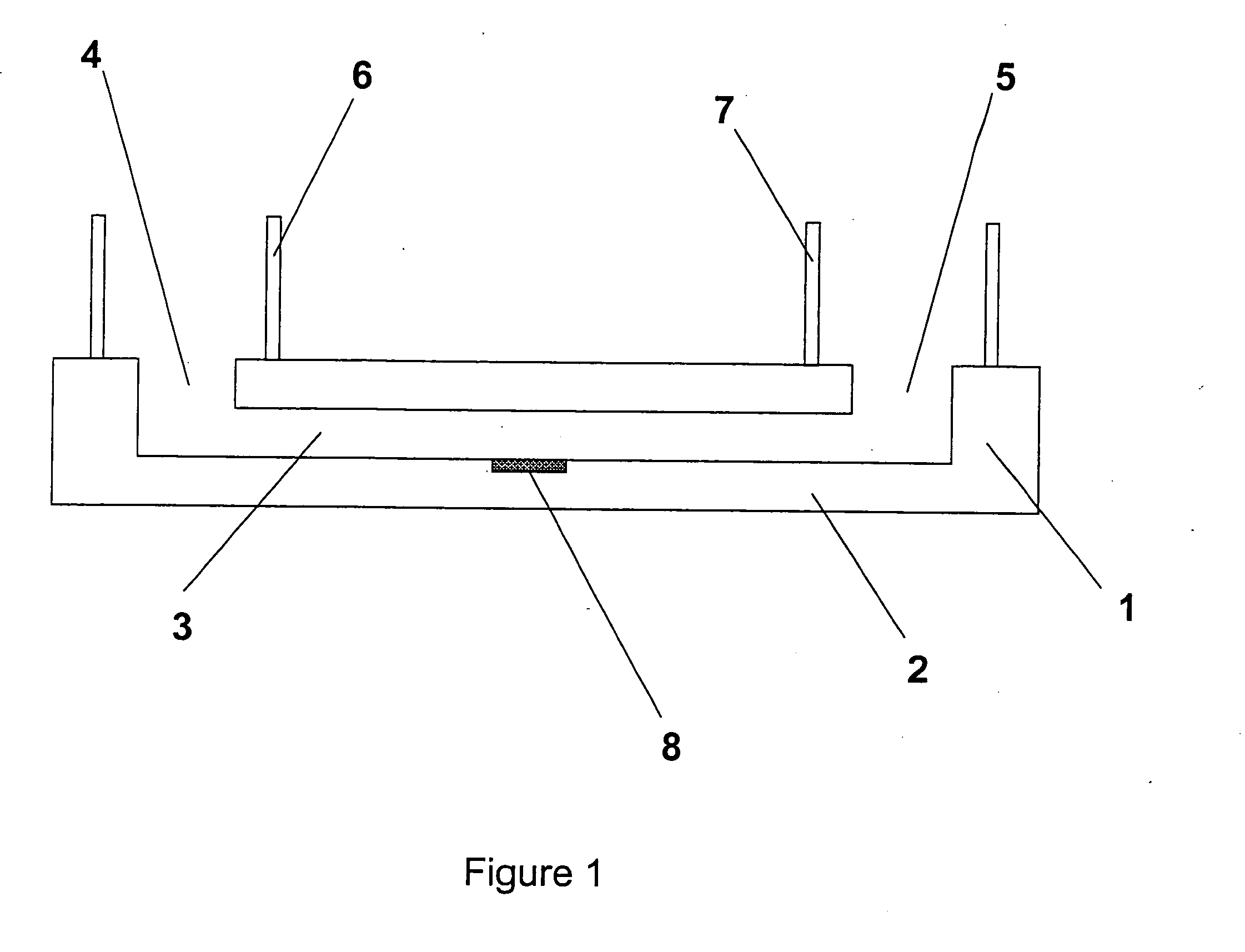
[0041]FIG. 1 shows a microfluidic device 1 (also referred to hereinafter as a microchip). Whilst a polymer-based microfluidic device is preferred, different devices, including glass, silicon, ceramic materials, etc can also be used.

[0042] The microchip 1 is composed of a body 2, said body comprising a covered microchannel 3 having a least one dimension compatible with laminar flow conditions. The covered microchannel has at least one inlet 4 and one outlet 5, the inlet and outlet each being composed of a hole, a tip or a venting material enabling the passage of fluids (gas or liquid). In this example, the inlet 4 and the outlet 5 are respectively surrounded by an inlet reservoir 6 and an outlet reservoir 7. A detector 8, comprising an integrated electrode, is in contact with the body 2 such as to enable the detection of changes due to the presence and / or the flow rate change of a fluid in the covered microchannel 3.

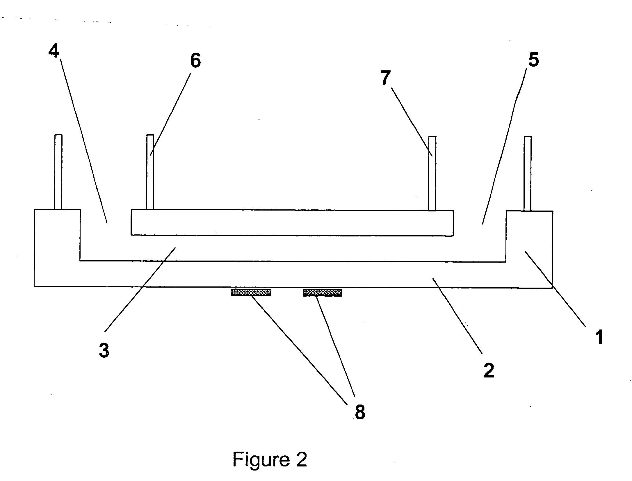
[0043]FIG. 2 shows a device similar to that shown in FIG. 2, but c...


PUM

PropertyMeasurementUnit
angleaaaaaaaaaa
currentaaaaaaaaaa
total currentaaaaaaaaaa

Abstract

An electrochemical flow monitoring device comprises a microfluidic system comprising at least one covered microchannel (3) having an inlet (4) and an outlet (5). A pressure difference is applied between the inlet and the outlet of the microfluidic system, for example by changing the relative heights of the inlet (4) and outlet (5), such as to generate a flow of solution within the microchannel (3). The microfluidic system has at least one electrode (8) for monitoring said flow of solution by measuring an electrochemical property of said solution.

Description

BACKGROUND TO THE INVENTION [0001] This invention relates to a microfluidic flow monitoring device and to a method of performing an analytical assay. [0002] Development of microfluidic devices for manipulating fluids has been a center of interest in research for more than 10 years. The use of microfluidics has become popular because it enables the analysis of minute quantities of fluid sample by means such as capillary electrophoresis or nanoelectrospray mass spectrometry. The applications of these “fluidic microchips” or microfluidic devices are numerous and reactions such as PCRs (polymerase chain reactions), hybridisations, immunoassays, syntheses etc have been developed on these microsystems. [0003] One constant preoccupation is to find a better way to induce and control the desired flow profile, flow direction and flow rate during the analyses. Some microfluidic systems work with interconnected covered microchannels which do not need valves to direct fluids in the right directi...

Claims


Application Information

Patent Timeline
Patent Type & Authority Applications(United States)
IPC IPC(8): G01F1/64G01N33/487B01L3/00G01F1/56G01F1/708G01N27/447
CPCB01L3/502707B01L3/50273B01L2300/0645G01F1/64B01L2400/0487G01F1/56B01L2400/0457
Inventor ROSSIER, JOEL STEPHANEMORIER, PATRICKREYMOND, FREDERIC
Owner DIAGNOSWISS
Why Eureka
Try Eureka