Railroad crossing surveillance and detection system

a detection system and surveillance technology, applied in the field of railroads, can solve the problems of inherently difficult to stop or arrest the motion of a train over short distances, the interaction between different forms of transportation causes dangers and risks, and the train travels at relatively high speed and has tremendous mass and thus tremendous momentum

Inactive Publication Date: 2007-02-22
STEVENSON BOB +1
View PDF1 Cites 50 Cited by
  • Summary
  • Abstract
  • Description
  • Claims
  • Application Information

AI Technical Summary

Problems solved by technology

Mixing forms of transportation results in dangers.
As this was true with pedestrians and animal drawn carriages and both with internal combustion engine cars and trucks later in history, the interaction between different forms of transportation causes dangers and risks.
Trains typically travel at relati

Method used


Image

  • Railroad crossing surveillance and detection system
  • Railroad crossing surveillance and detection system
  • Railroad crossing surveillance and detection system

Examples


Embodiment Construction

[0016] It will be understood by those skilled in the art that the present invention can be implemented in a number of different ways, within the scope of this application. A presently preferred embodiment of the invention will now be described below.

Overview

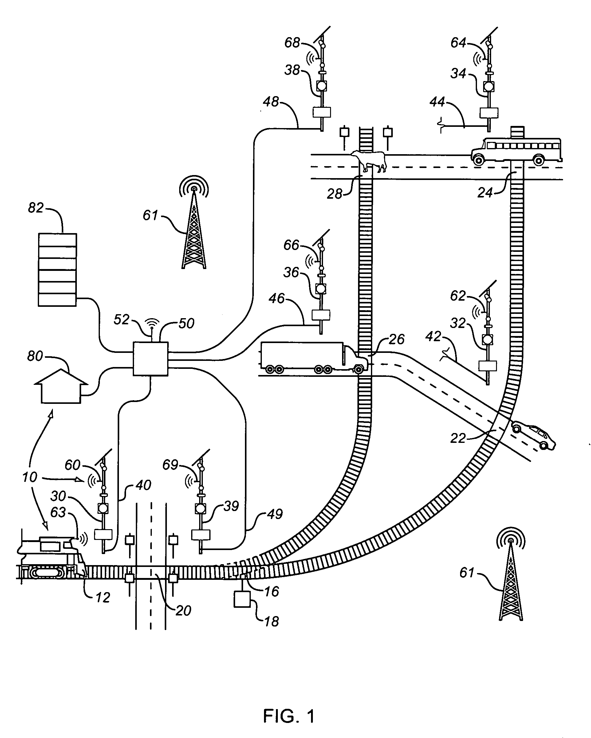
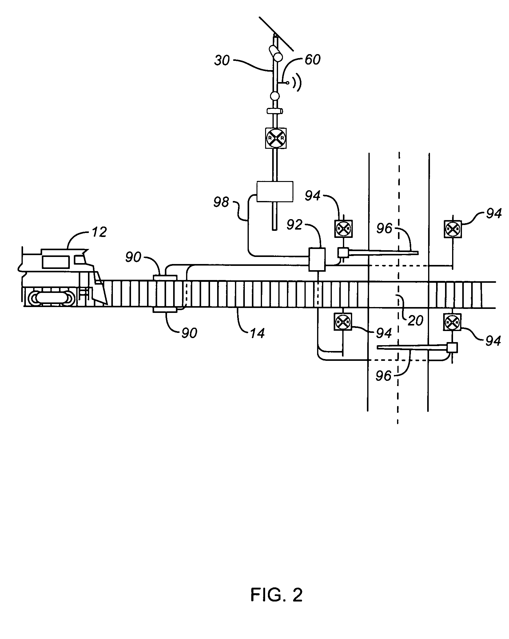
[0017]FIG. 1 illustrates at a general level the railroad surveillance and detection system 10. The train engine 12 is illustrated on a section of track 14 before with a fork 16 controlled by a track switch 18 and a series of conventional road crossings 20, 22, 24, 26, 28. At each crossing 20, 22, 24, 26, 28 there is a corresponding monitoring station 30, 32, 34, 36, 38. There is also a monitoring station 39 proximate to the switch 16. The monitoring locations are exemplar. It may be appropriate for monitors to be located in other locations along the track which may be generate a safety risk or a higher probability as a target for terrorists or groups or individuals engaged in mischief. It may also be desirable to maintain monit...


PUM


Abstract

A railroad remote monitoring and detection system employing cameras, that may or may not be remotely positionable and repositionable, and other motion and presence detection devices such as millimeter wave radar and/or passive infrared and or ultrasound detectors. The use of multiple sensor devices reduces the occurrence of false alarms. The system employs software and logic to detect predetermined alarm conditions and then send a signal to a local or central command center and trains on the route. The system includes wireless receivers onboard the train that scan for monitor information one or more monitor stations in advance of the trains progress to give the train engineer/driver advanced warning of hazardous conditions on the trains route. Alarms to the central control center can be monitored to determine a recurrence of potentially hazardous conditions at a particular site so that steps can be taken to avoid such conditions in the future.

Description

CROSS-REFERENCE TO RELATED PATENT APPLICATIONS [0001] This patent application claims the benefit of U.S. Provisional Patent Application No. 60 / 672,564, filed Apr. 18 2005, entitled “Railroad Crossing Surveillance and Detection System”[0002] Any references cited hereafter are incorporated by reference to the maximum extent allowable by law. To the extent a reference may not be fully incorporated herein, it is incorporated by reference for background purposes and indicative of the knowledge of one of ordinary skill in the art. TECHNICAL FIELD OF THE DISCLOSURE [0003] The present invention relates generally to the field of railroad. More particularly to railroad monitoring and threat detection systems. BACKGROUND OF THE DISCLOSURE [0004] Railroads play a vital role in the transportation of goods and people. However, it is not the only form of transportation and is normally found mixed with other forms of transportation. Mixing forms of transportation results in dangers. As this was tru...

Claims


Application Information

Patent Timeline
IPC IPC(8): B61L23/34
CPCB61L29/30
Inventor STEVENSON, BOBCALIXTO, PAUL
Owner STEVENSON BOB
Why Eureka
Try Eureka