
Recliner adjuster

a recliner and adjuster technology, applied in the field of recliner adjusters, can solve the problems of difficult reduction of size, increase in size of recliner adjusters, and difficulty in reducing size, and achieve the effect of increasing the diameter of internal teeth of internal gears and increasing locking strength

Inactive Publication Date: 2007-02-22
DELT IND
View PDF25 Cites 33 Cited by
  • Summary
  • Abstract
  • Description
  • Claims
  • Application Information

AI Technical Summary

Benefits of technology

[0013] It is accordingly an objective of the present invention to provide a compact recliner adjuster capable of increasing the locking strength without increasing the size thereof.
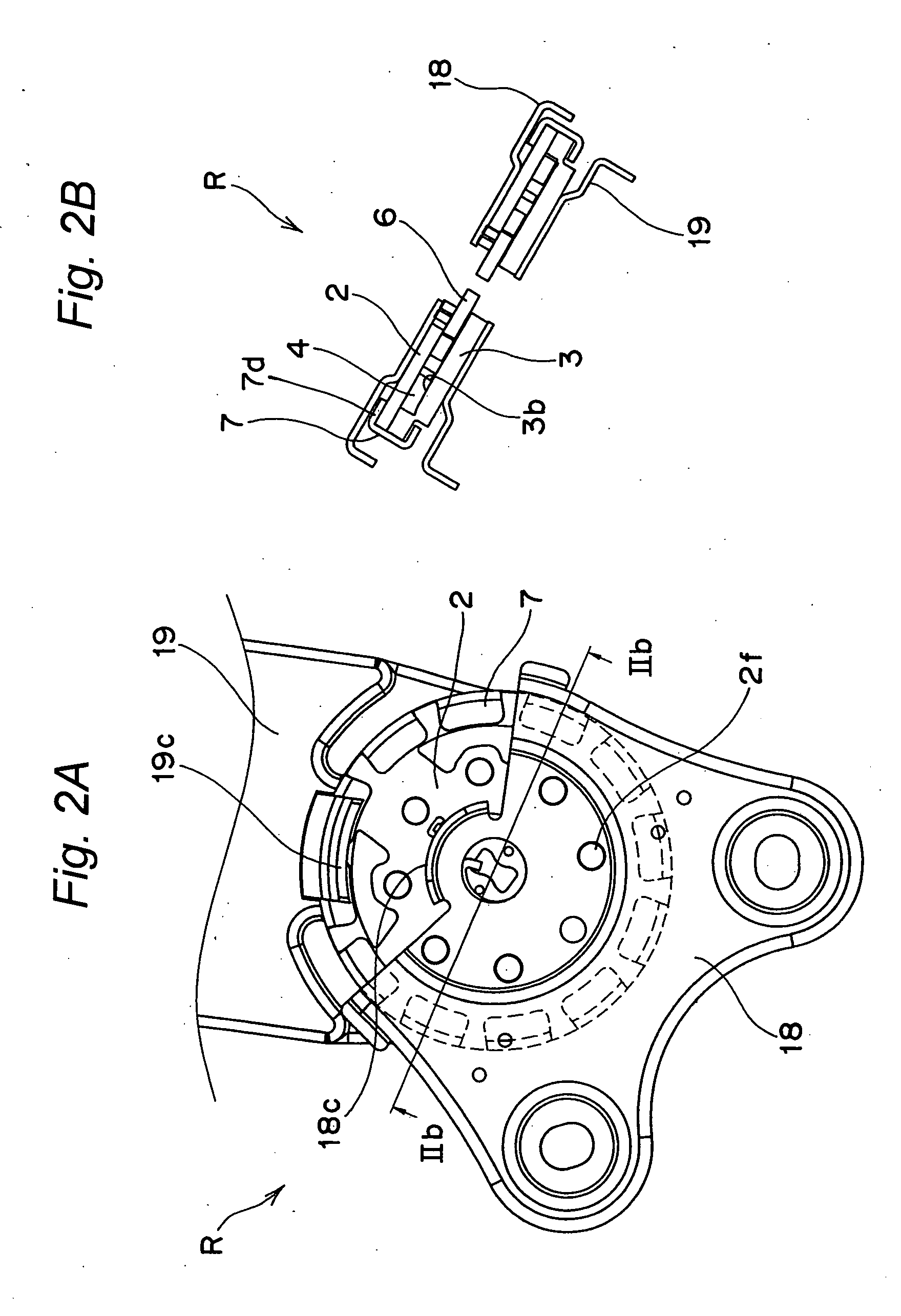
[0017] According to the present invention, because the outer peripheral surface of the internal gear is held in sliding contact with the inner surface of the cylindrical side portion of the mounting ring to thereby radially position the internal gear, if the guide bracket has an outer diameter equal to that of a guide bracket mounted in the recliner adjuster as disclosed in Document 2, the diameter of the internal teeth of the internal gear can be increased, making it possible to provide a compact recliner adjuster having an increased locking strength without increasing the size thereof.

Problems solved by technology

This construction makes the recliner adjuster thick, making it difficult to reduce the size thereof.
Further, the diameter of the internal teeth must be increased to enhance the locking strength, resulting in an increase in size of the recliner adjuster.

Method used


Image

  • Recliner adjuster
  • Recliner adjuster
  • Recliner adjuster

Examples


Embodiment Construction

[0028] This application is based on an application No. 2004-195748 filed Jul. 1, 2004 in Japan, the content of which is herein expressly incorporated by reference in its entirety.

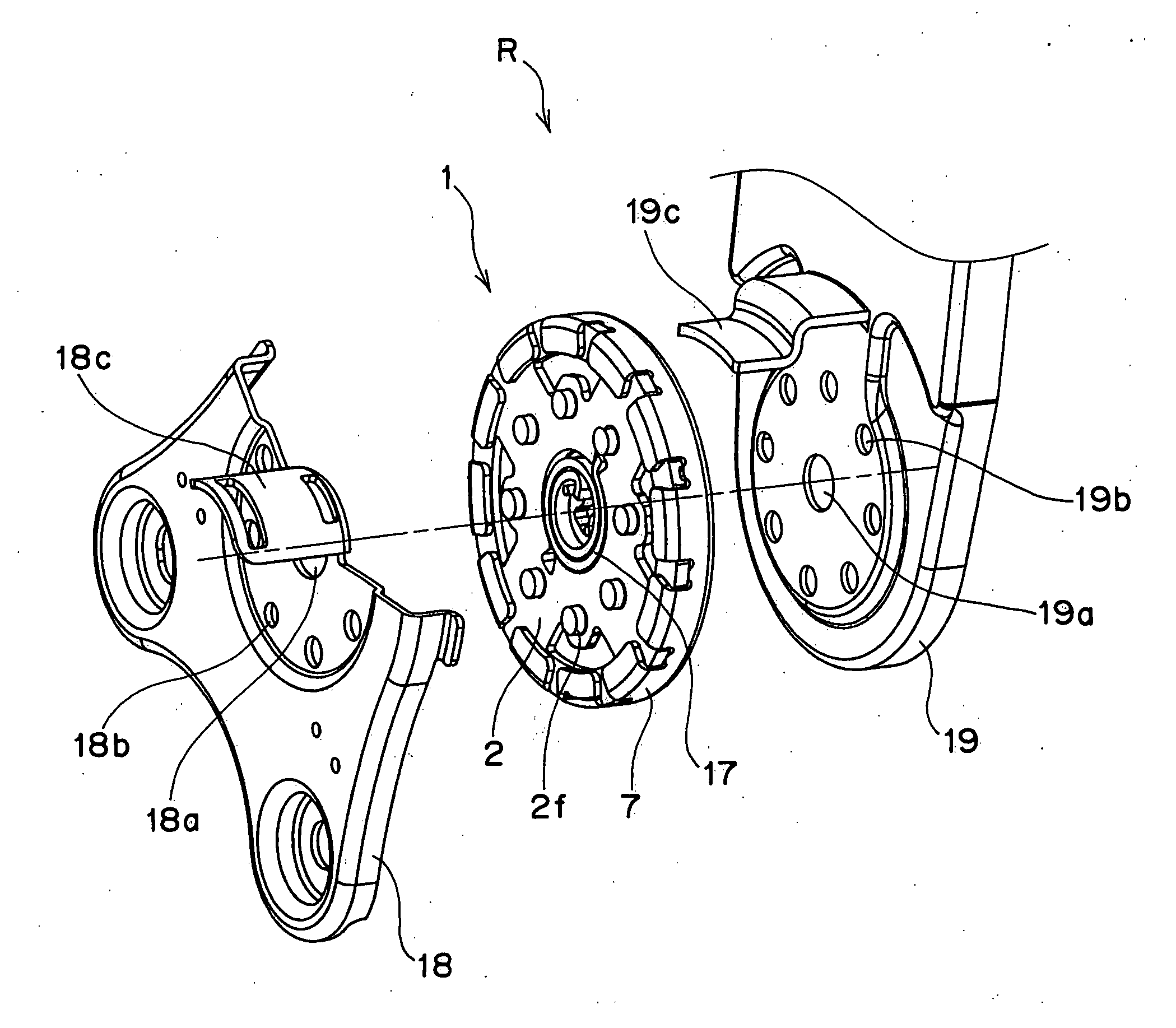
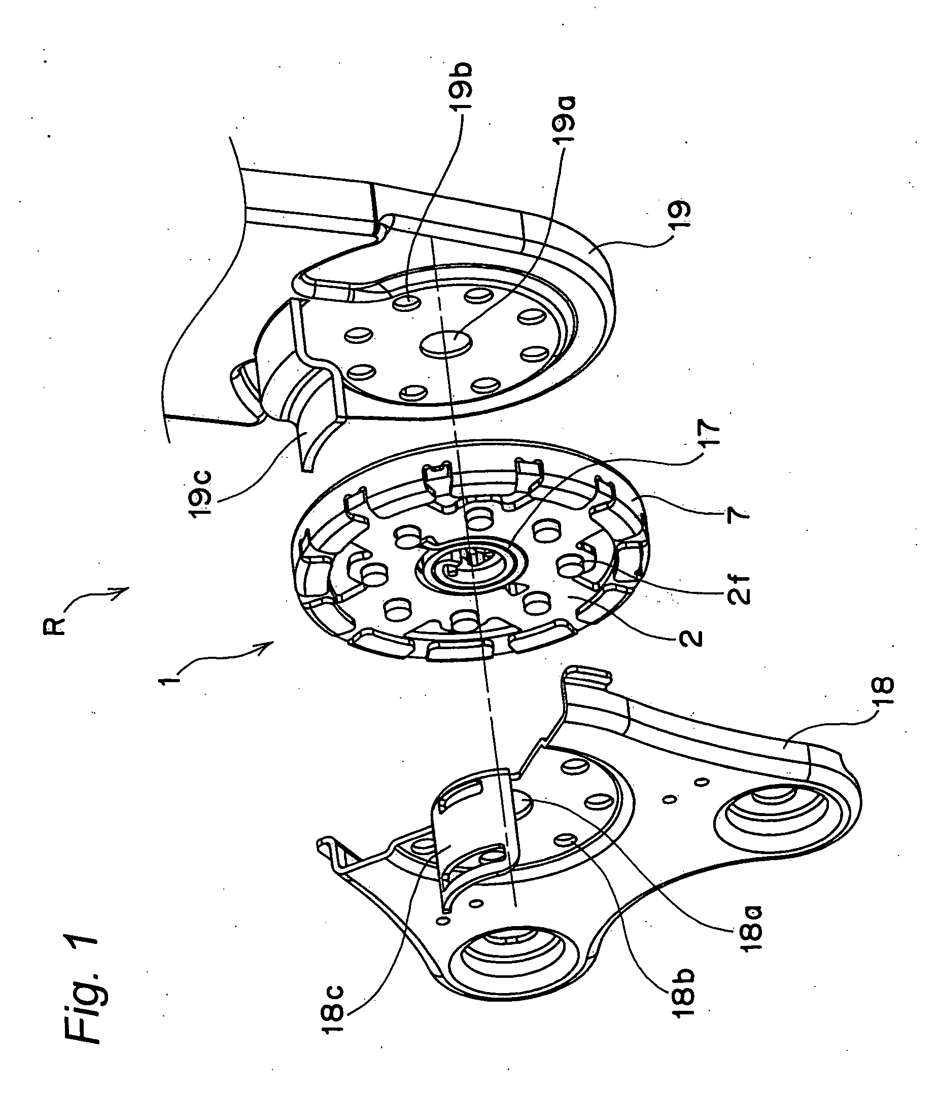
[0029]FIG. 1 and FIGS. 2A and 2B depict a recliner adjuster R according to the present invention, which is to be mounted on respective sides of, for example, an automobile seat. The recliner adjuster R is intended to change inclination of a seat back (not shown) relative to a seat cushion (not shown).

[0030] The recliner adjuster R includes a generally round recliner assembly 1 mounted on a connecting portion between the seat cushion and the seat back. As shown in FIG. 3, FIGS. 4A-4C and FIGS. 5A and 5B, the recliner assembly 1 includes a guide bracket 2 to be secured to the seat cushion, an internal gear 3 to be secured to the seat back so as to confront the guide bracket 2, a pair of lock gears 4 interposed between the guide bracket 2 and the internal gear 3, a pair of auxiliary lock gears5 interposed be...


PUM


Abstract

A recliner adjuster for adjusting an inclination of a seat back with respect to a seat cushion includes a guide bracket to be secured to one of the seat cushion and the seat back, an internal gear to be secured to the other of the seat cushion and the seat back, a cam interposed between the guide bracket and the internal gear, a pair of lock gears interposed between the guide bracket and the internal gear so as to be radially slidable in association with movement of the cam, and a mounting ring for mating the guide bracket and the internal gear with each other with the cam and the pair of lock gears accommodated therein. The mounting ring has a generally flat annular portion, a cylindrical side portion, and a plurality of bent portions formed at a distal end of the cylindrical side portion. The guide bracket and the internal gear are sandwiched between the generally flat annular portion and the plurality of bent portions of the mounting ring, and an outer peripheral surface of the internal gear is held in sliding contact with an inner surface of the cylindrical side portion of the mounting ring, thereby radially positioning the internal gear.

Description

BACKGROUND OF THE INVENTION [0001] 1. Field of the Invention [0002] The present invention relates to a recliner adjuster attached to, for example, an automobile seat for appropriately adjusting inclination of a seat back with respect to a seat cushion. [0003] 2. Description of the Related Art [0004] A recliner adjuster is interposed between a seat cushion and a seat back that can be inclined relative to the seat cushion. A conventional recliner adjuster generally includes a first bracket (or a lower arm) fixed to the seat cushion and a second bracket (or an upper arm) fixed to the seat back so as to be rotatable relative to the first bracket. [0005] This recliner adjuster also includes a cam interposed between the first and second brackets and coupled to a support shaft, which is concentric with a center of rotation of the second bracket relative to the first bracket, for rotation together therewith. The cam is intended to radially slide, upon rotation of the support shaft, a lock g...

Claims


Application Information

Patent Timeline
Patent Type & Authority Applications(United States)
IPC IPC(8): B60N2/02
CPCB60N2/236
Inventor OKI, YASUKAZU
Owner DELT IND
Learn More