Broach

a technology of broach and spherical plate, which is applied in the field of broach, can solve the problems of easy to become apparent, and difficult to secure machining accuracy, so as to increase the machining accuracy of cutting, and facilitate the manufacturing of broach

Active Publication Date: 2014-10-02
MITSUBISHI MATERIALS CORP
View PDF10 Cites 4 Cited by
  • Summary
  • Abstract
  • Description
  • Claims
  • Application Information

AI Technical Summary

Benefits of technology

[0029]According to the configuration of the broach, it is possible to dispose the round teeth group on the front-end section in the forming region of the cutting edges of the broach body. Therefore, when the manufacturing of the broach is difficult, for example, when the tooth groove width of the spline teeth is narrow and a prepared hole of the work material is machined into an internal gear shape, the configuration is useful for facilitating the manufacturing the broach. As in the configuration of the present invention described above, the internal diameter of the prepared hole is increased in size by disposing the round teeth group closer to the front than the spline teeth group and cutting the smaller-diameter (the inner circumference portion) of the prepared hole first using the round teeth group. If the subsequent spline teeth group is caused to cut into the work material from this state, the tooth groove width of the spline teeth is widened and the manufacturing of the broach is simplified.
[0030]According to the broach of the present invention, it is possible to sufficiently increase the machining accuracy of the cutting.

Problems solved by technology

That is, in the broach of Japanese Patent No. 3377713, misregistration (center shift) occurs at the cutting section of the cutting edges of the shell section in relation to the section of the work material to be cut by the cutting edges of the broach body due to the influence of a clearance or the like that is provided to attach the shell section to the broach body; thus, it is difficult to secure machining accuracy.
In particular, in the case of a broach with rear round teeth, it is difficult to secure the machining accuracy of the round teeth group that is formed at the rear side of the tool feed direction, and the problems described above easily become apparent.
Therefore, in the related art, there is little demand for accuracy in the machining of the inner circumference in comparison with grooving accuracy, and even for those skilled in the art, the problems described above had not been clearly identified.

Method used


Image

  • Broach
  • Broach
  • Broach

Examples


Embodiment Construction

[0033]Hereinafter, description will be given of a broach 1 according to an embodiment of the present invention, referring to the drawings.

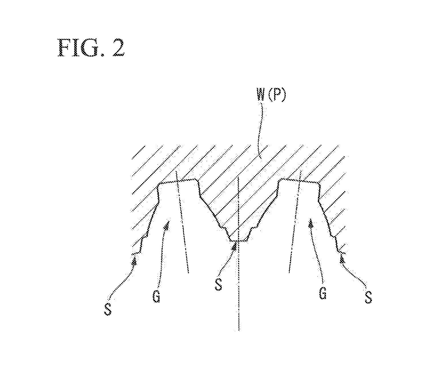
[0034]The broach 1 of the present embodiment is a broach with rear round teeth, which subjects a prepared hole that is formed in a work material in advance to grooving and machining of the inner circumference, in order, to form the prepared hole in an internal gear shape (a predetermined shape). Specifically, the broach 1 is a helical broach, and as shown in FIG. 2, the broach 1 broaches a work material W that will become a product such as a helical internal gear P having a twisted groove G at the inner circumference thereof. An example of the helical internal gear P is a planetary internal gear for an automatic transmission.

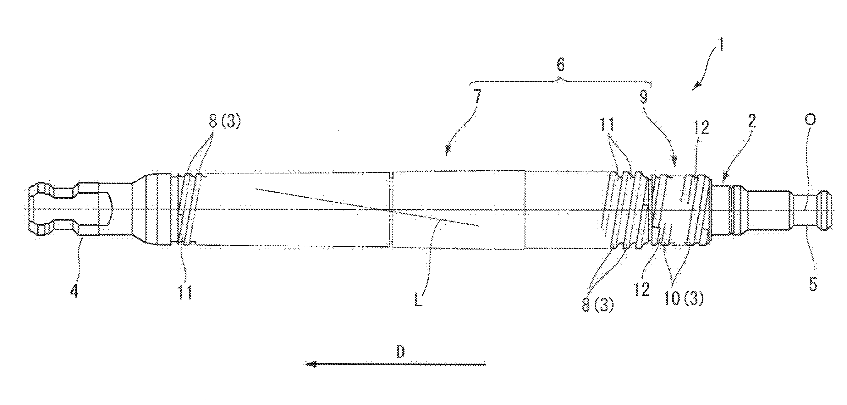
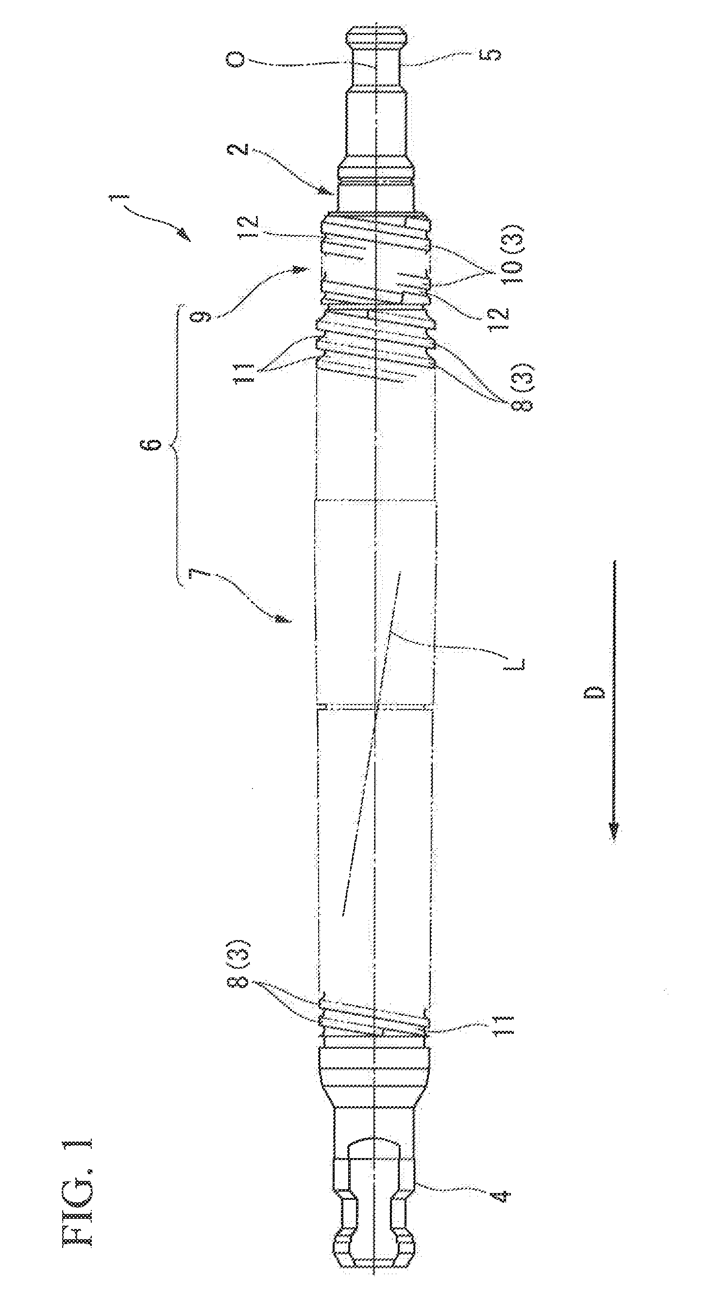
[0035]As shown in FIG. 1, the broach 1 is provided with a shaft-shaped broach body 2 and a plurality of cutting edges 3 that are arranged around the outer circumference of the broach body 2 spaced apart at intervals in an axis...


PUM

PropertyMeasurementUnit
circumferenceaaaaaaaaaa
outer circumferenceaaaaaaaaaa
shapeaaaaaaaaaa

Abstract

A plurality of cutting edges that are arranged on an outer circumference of a shaft-shaped broach body are provided with a spline teeth group, which contains a plurality of spline teeth 8 that groove a prepared hole of a work material, and a round teeth group, which is disposed in a different position from the spline teeth group along an axis direction and contains a plurality of round teeth that machine an inner circumference of the prepared hole. At least one gullet is formed to extend along the outer circumference of the broach body in a circumferential direction around the axis between the round teeth that are adjacent to one another in the axis direction in the round teeth group. The gullet extends toward the axis direction, gradually twisting toward the circumferential direction. The spline teeth group and the round teeth group are formed integrally on the outer circumference of the broach body.

Description

BACKGROUND OF THE INVENTION[0001]1. Field of the Invention[0002]The present invention relates to a broach in which a plurality of cutting edges are formed on a broach body. The cutting edges of the broach are inserted, together with the broach body, into a prepared hole formed in a work material, in order, to form the prepared hole in a predetermined shape such as an internal gear shape using grooving or machining of the inner circumference.[0003]Priority is claimed on Japanese Patent Application No. 2013-070820, filed on Mar. 29, 2013, the content of which is incorporated herein by reference.[0004]2. Description of Related Art[0005]As such a broach of the related art, there is known a broach that is provided with a shaft-shaped broach body and a plurality of cutting edges that are arranged on an outer circumference of the broach body spaced apart at intervals in an axial direction of the broach body. The broach body is inserted into a prepared hole that is formed in the work materi...

Claims


Application Information

Patent Timeline
Patent Type & Authority Applications(United States)
IPC IPC(8): B23D43/06
CPCB23D43/06B23D43/005B23D37/00Y10T407/16Y10T407/1671
Inventor YOSHIZUMI, NAOKIKOBAYASHI, YOSHIOKOHNO, KENSUKE
Owner MITSUBISHI MATERIALS CORP
Why Eureka
Try Eureka