Thermal activation apparatus and printer including the same

a technology of activation apparatus and printer, which is applied in the direction of manual label dispensers, transportation and packaging, packaging, etc., can solve the problems of affecting the discharge of heat-sensitive adhesive labels, clogging of sensitive adhesive labels, etc., and achieve the effect of reducing the loss of advance amoun

Inactive Publication Date: 2006-06-22
SEIKO INSTR INC
View PDF2 Cites 2 Cited by
  • Summary
  • Abstract
  • Description
  • Claims
  • Application Information

AI Technical Summary

Benefits of technology

[0016] According to a first aspect of the present invention, by disposing a pair of shafts at given intervals from each other in a loop made by an endless elastic belt such that the internal diameter of the elastic belt is increased, the elastic belt is held under tension. When the belt is moved by driving one of the shafts to rotate by drive means with this state maintained, tension difference of the belt is caused between a place where the belt is in contact with the shafts and a place where the belt is not in contact with the shafts, and between a place where the belt is in contact with the driving shaft and a place where the belt is in contact with the driven shaft, and thus, the belt is expanded and contracted in places. In other words, this has the effect of squeezing the belt in places. Therefore, even when residue of adhesive on the back side of a heat-sensitive adhesive label sticks to the surface of the belt during the heat-sensitive adhesive label is discharged, it is of ten the case that the stuck residue scales off by the expanding and contracting action of the belt, and thus, does not accumulate above a certain level and a discharge path is not clogged by the residue.
[0017] In the above-described thermal activation apparatus, it is preferable that a pulley is provided for both or either of the shafts. With this structure, since the pulley(s) prevent(s) slippage between the shafts and the belt, it is possible to decrease the loss of the amount of advance of the belt due to slippage when the label is discharged.

Problems solved by technology

However, even in the conventional case of the discharge roller where a material such as fluoroplastic to which an adhesive is difficult to stick is used as the O ring, once adhesive residue adheres to the perimeter of the O ring, and since additional residue accumulates on the attached residue, the discharge path of the heat-sensitive adhesive label may be clogged in the course of time, which adversely affects discharge of the heat-sensitive adhesive label.

Method used


Image

  • Thermal activation apparatus and printer including the same
  • Thermal activation apparatus and printer including the same
  • Thermal activation apparatus and printer including the same

Examples


Embodiment Construction

[0029] Embodiment of the present invention will be described with reference to the drawings.

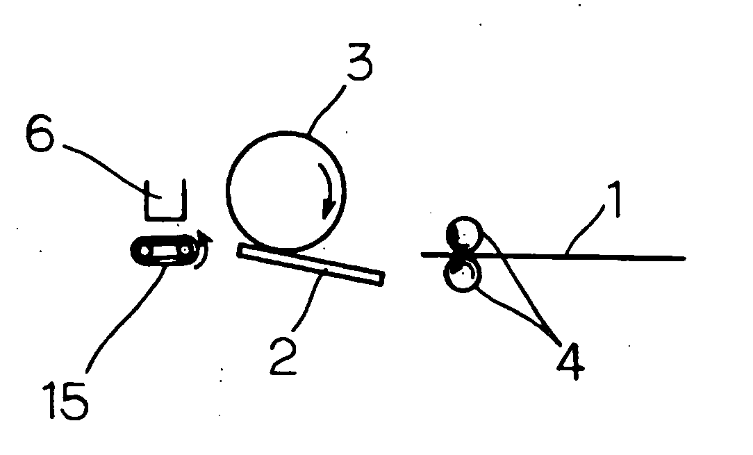
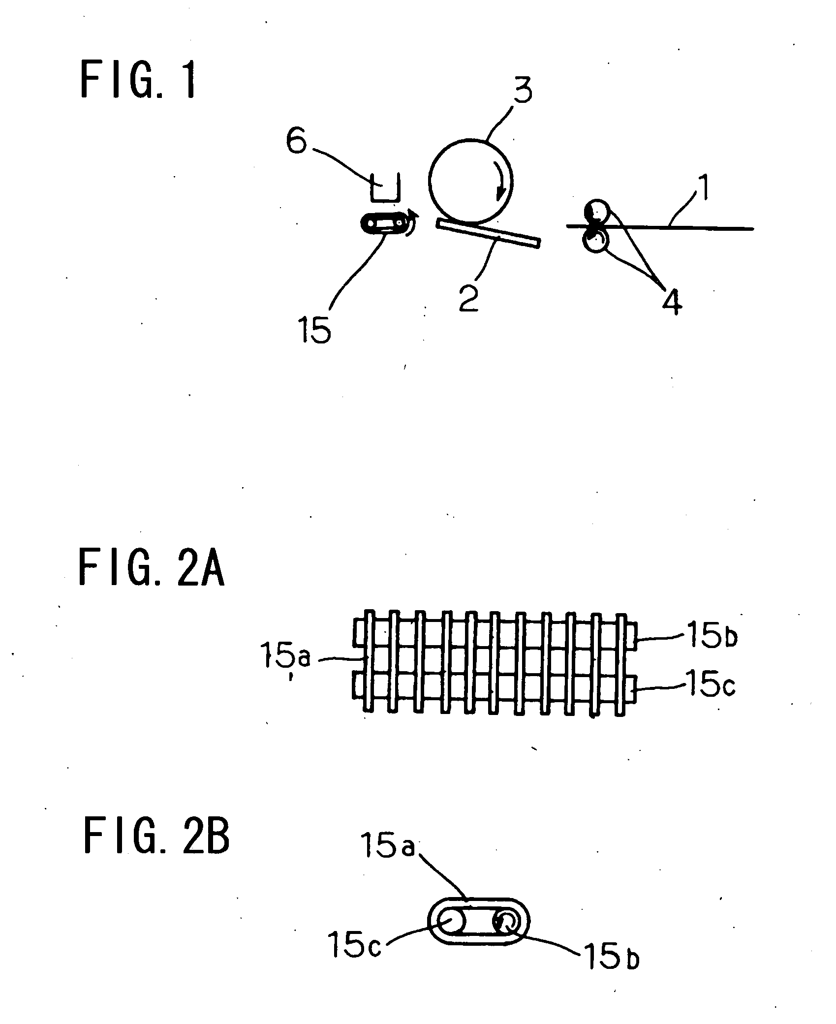
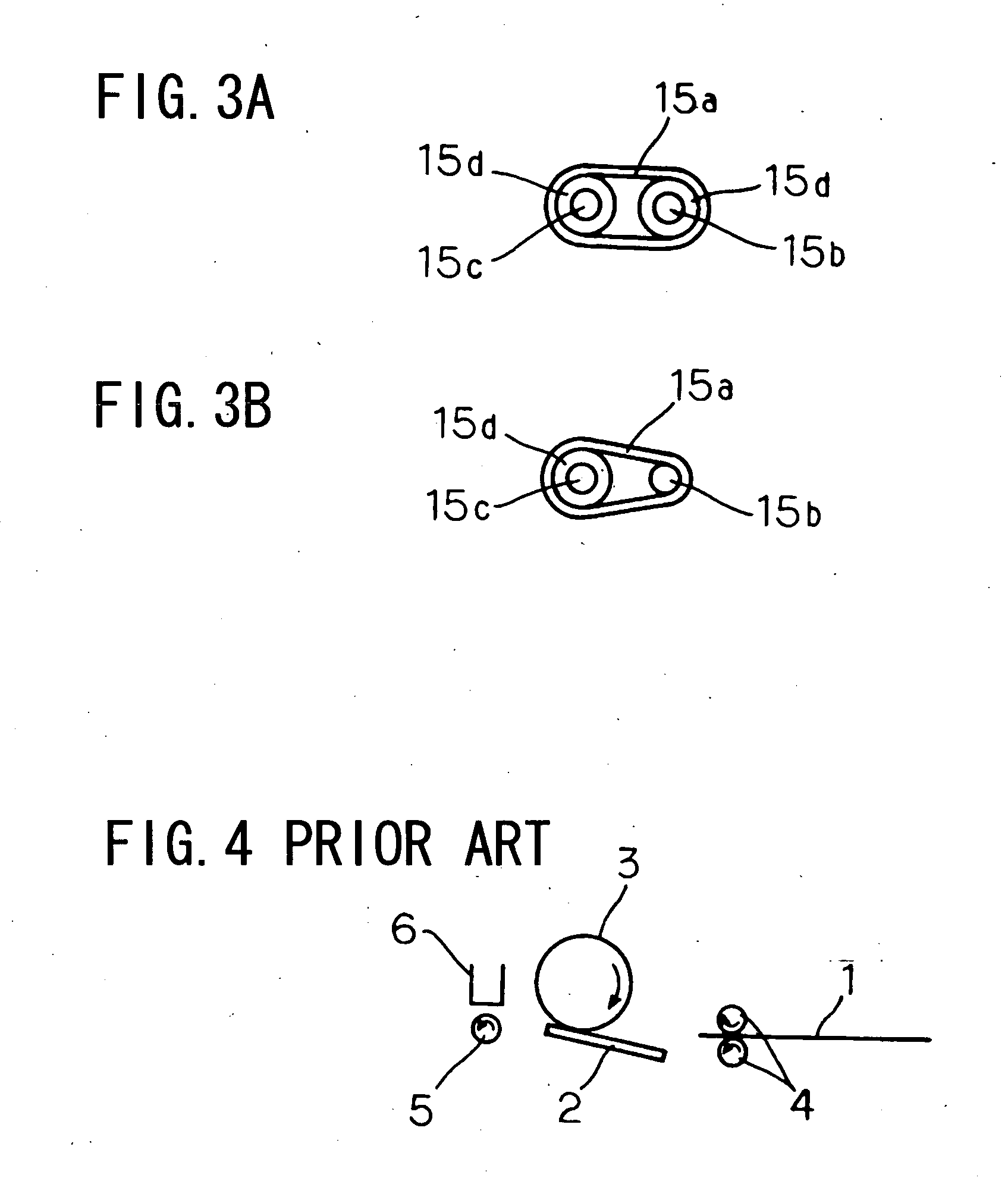
[0030]FIG. 1 is a schematic sectional view illustrating a structure of a thermal activation apparatus according to an embodiment of the present invention. In FIG. 1, elements similar to those in FIG. 4 are designated by the same reference numerals.

[0031] As illustrated in FIG. 1, a thermal activation apparatus of this embodiment includes a thermal head 2 as a heating head having heating elements for heating a heat-sensitive adhesive agent layer formed on the back side of a heat-sensitive adhesive label 1, a platen roller 3 for transporting the heat-sensitive adhesive label 1 with the heating elements of the thermal head 2 in contact with the heat-sensitive adhesive label 1, insert rollers 4 for inserting the heat-sensitive adhesive label 1 between the thermal head 2 and the platen roller 3, and a discharge mechanism 15 for completely discharging from between the thermal head 2 and the plate...


PUM

PropertyMeasurementUnit
heat-sensitiveaaaaaaaaaa
adhesionaaaaaaaaaa
internal diameteraaaaaaaaaa

Abstract

Provided is a thermal activation apparatus in which a discharge path of a heat-sensitive adhesive label is not adversely affected by adhesive residue. The thermal activation apparatus comprises a discharge mechanism (15) for completely discharging a heat-sensitive adhesive label with its heat-sensitive adhesive agent layer formed on the back side heated by a thermal head from between the thermal head and a platen roller. The discharge mechanism (15) is structured such that two shafts (15b and 15c) made of metal are passed through a plurality of belts (15a) which are endless elastic members, the two shafts (15b and 15c) are disposed at given intervals from each other and in parallel with each other, and the two shafts (15b and 15c) are rotatably supported. By rotating one of the two shafts (15b and 15c) as a driving shaft, the belts (15a) rotate to be able to discharge the heat-sensitive adhesive label (1) fed thereonto.

Description

BACKGROUND OF THE INVENTION [0001] 1. Field of the Invention [0002] The present invention relates to a thermal activation apparatus for transporting a sheet material having a thermally activated adhesive surface formed on one side thereof, which becomes adhesive when heated, and for heating the thermally activated adhesive surface of the sheet material, and to a printer including the same. [0003] 2. Description of the Related Art [0004] These days, an adhesive label for a bar code, a price tag, or the like which often has an adhesive agent layer formed on the back side of a recording surface (printing surface), is stored with backing paper or a release liner stuck thereon to temporarily adhere the adhesive to the backing paper or the release liner. However, this type of an adhesive label is inconvenient because it is necessary to peel off the release liner from the adhesive agent layer when the label is used and waste is inevitably generated. [0005] For this reason, as a system wher...

Claims


Application Information

Patent Timeline
Patent Type & Authority Applications(United States)
IPC IPC(8): B32B37/00
CPCY10T156/17B65C9/25
Inventor TAKAHASHI, MASANORIHOSHINO, MINORUKOHIRA, HIROYUKIOBUCHI, TATSUYASATO, YOSHINORI
Owner SEIKO INSTR INC
Why Eureka
Try Eureka