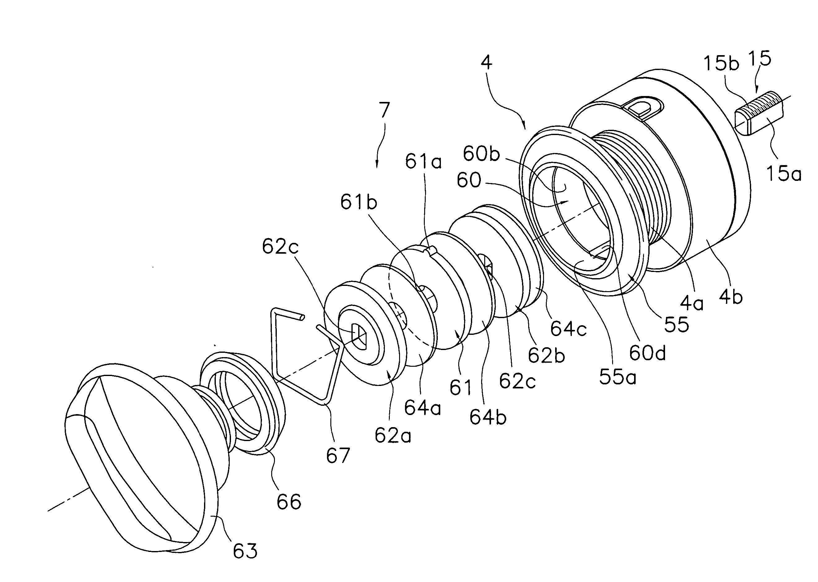
[0013] With this drag mechanism, when, for example, one first drag washer is installed between two second drag washers, first a second drag washer is installed into the drag housing recess with the
flange fastening member already installed into the internal circumferential surface of the
bobbin trunk. Next, the first drag washer is oriented such that the
interlock protrusion is aligned with one of the
interlock grooves and tilted such that the interlock protrusion enters the drag housing recess ahead of the rest of the first drag washer. Thus oriented, the first drag washer is then passed through the inside of the tubular section and installed into the internal circumferential surface of the
bobbin trunk. Next, the other second drag washer is inserted. Finally, the drag knob is installed to complete the
assembly of the drag mechanism. Since the one or more interlock protrusions provided on the first drag washer are arranged within an angular phase of 90 degrees or less, the
maximum dimension of the first drag washer (i.e., the length of the longest
line segment joining two points on the outside circumference of the washer) is shorter than the
maximum dimension of a conventional first drag washer having two interlock protrusions arranged on diametrically opposite sides of the washer (i.e., the distance between the outermost edges of the two interlock protrusions of a conventional second drag washer). As a result, the first drag washer can be tilted to a smaller degree than the conventional first drag washer when it is tilted in order to pass it through the tubular section and, thus, the length that the tilted first drag washer assumes in the longitudinal direction (axial direction) can be shortened. In this way, the internal diameter of the drag housing recess can be increased even if the longitudinal length of the same is shorter.
[0014] A
spinning reel drag mechanism in accordance with a second aspect of the present invention is a drag mechanism according to the first aspect, wherein the number of said interlock protrusions is one. With this drag mechanism, since there is only one interlock protrusion, the longitudinal dimension (
axial length) assumed by the first drag washer when it is tilted is shorter than longitudinal dimension that results when a plurality of interlock protrusions is provided. As a result, the internal diameter of the drag housing recess can be increased even more in relation to the longitudinal length of the drag housing recess.
[0015] A
spinning reel drag mechanism in accordance with a third aspect of the present invention is a drag mechanism according to the first or second aspect, wherein a seal member is arranged between the drag knob and the flange fastening member, the seal member serving to prevent liquids from penetrating to the drag disks. Since the flange fastening member has a tubular section, the drag housing recess can be sealed by merely installing a seal member between the internal circumferential surface of the tubular section and the external circumferential surface of the drag knob. As a result, a simple structure can be employed to reliably prevent the drag force from changing due to wetness.
[0016] A spinning reel drag mechanism in accordance with a fourth aspect of the present invention is a drag mechanism according to the first, second, or third aspect, wherein a drag disk is arranged between the first and second drag washers. Arranging a drag disk between the washers enables smooth slippage to occur between the washers when the drag mechanism is operated.
[0018] With the present invention, the first drag washer has one interlock protrusion arranged on an outer circumferential portion thereof or a plurality of such interlock protrusions arranged within an angular phase of 90 degrees or less. Consequently, the
maximum dimension of the first drag washer (i.e., the length of the longest
line segment joining two points on the outside circumference of the washer) is shorter than the maximum dimension of a conventional first drag washer having two interlock protrusions arranged on diametrically opposite sides of the washer (i.e., the distance between the outermost edges of the two interlock protrusions of a conventional second drag washer). As a result, the first drag washer can be tilted to a smaller degree than the conventional first drag washer when it is tilted in order to pass it through the tubular section and, thus, the length that the tilted first drag washer assumes in the longitudinal direction (axial direction) can be shortened. In this way, the internal diameter of the drag housing recess can be increased as much as possible even if the longitudinal length of the same is shorter.

