Surface coil arrangement for magnetic resonance tomographs

Inactive Publication Date: 2007-02-22
SIEMENS HEALTHCARE GMBH
View PDF15 Cites 15 Cited by
  • Summary
  • Abstract
  • Description
  • Claims
  • Application Information

AI Technical Summary

Benefits of technology

[0011] An object of the present invention is to provide a surface coil arrangement of the above type that all

Problems solved by technology

This leads to a signal discontinuity in the middle of the body of the patient.
By contrast, if the patient is extremely thin or a child, the coil is too large for the patient.
The coil edges rest on the examination table; the coil cannot be optimally fixed.
Nevertheless, due

Method used


Image

  • Surface coil arrangement for magnetic resonance tomographs
  • Surface coil arrangement for magnetic resonance tomographs
  • Surface coil arrangement for magnetic resonance tomographs

Examples


Embodiment Construction

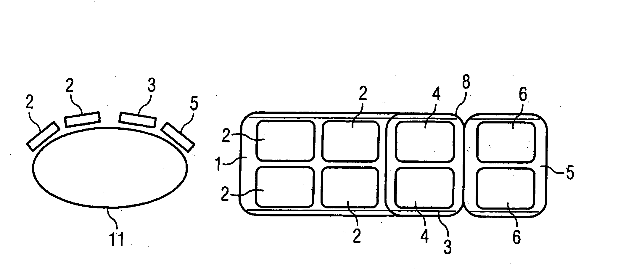
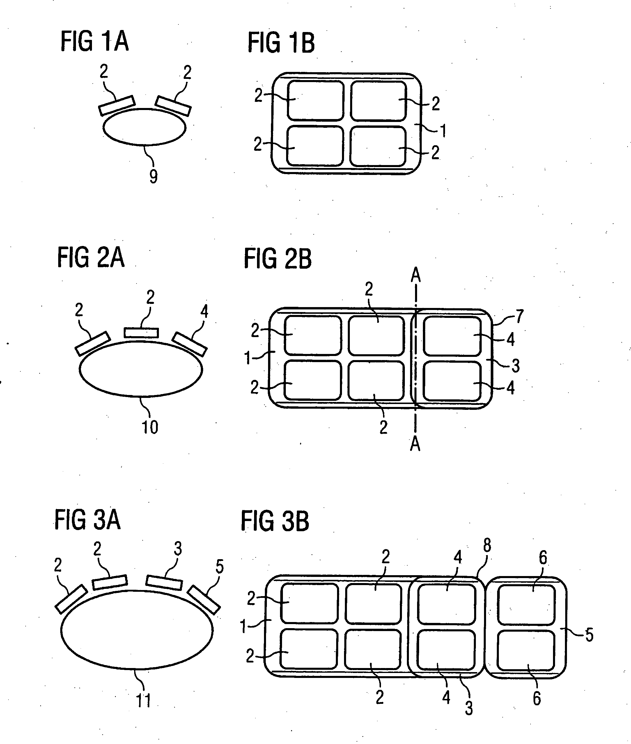
[0020]FIG. 1a schematically shows a cross-section through a region 9 of a patient body to be examined, on which region 9 a known surface coil arrangement (in the following: body array) rests. In this section one sees two coil elements 2 can be seen that, given the shown body cross-section 9, are adequate to expose this sufficiently or to acquire signals.

[0021]FIG. 1b shows the body array in a plan view. Two coil elements 2 are respectively arranged in two rows on an antenna 1 such that they likewise form two columns. The antenna 1 can be formed of a flexible material in order to be able to better adapt it to the body contours, can be formed of comprise a rigid material that has a curved shape adapted to the body contour.

[0022]FIG. 2 shows an inventive extended body array in which (as can be seen in FIG. 2b) a further body array with coil elements 4 that are arranged in a column is arranged on the right side on an antenna 1 according to FIG. 1b. As can be seen in FIG. 2a, a patient...


PUM


Abstract

A surface coil arrangement of a gradient system for an MR tomography apparatus has coil elements mounted on a first antenna, the antenna being extendable by at least one further antenna that likewise includes an arrangement of at least one coil element, and which is detachably or movably fastened to the first antenna.

Description

BACKGROUND OF THE INVENTION [0001] 1. Field of the Invention [0002] The present invention concerns a surface coil arrangement for a magnetic resonance tomography of the type wherein an arrangement of coil elements is mounted on an antenna, and wherein the antenna can be extended in size by at least one further antenna element that likewise carries an arrangement of at least one coil element. [0003] 2. Description of the Prior Art [0004] A surface coil arrangement of the above general type is known from PCT Application WO 03 / 025607 A1. [0005] Such surface coil arrangements are used in magnetic resonance tomography (MRT), as reception coil systems and possibly at the same time as transmission coils, for which purpose they are placed directly at the region to be examined on the body surface of a patient examined in the MR tomography apparatus. The examination subject is thereby exposed essentially from only one side, i.e., signals are acquired only on one side. In order to counteract t...

Claims


Application Information

Patent Timeline
IPC IPC(8): G01V3/00
CPCG01R33/34084G01R33/3415
Inventor WOHLFARTH, KATRIN
Owner SIEMENS HEALTHCARE GMBH
Why Eureka
Try Eureka