Geographic and space positioning system and process

Inactive Publication Date: 2007-02-22
KAUFMANN PIERRE
View PDF5 Cites 0 Cited by
  • Summary
  • Abstract
  • Description
  • Claims
  • Application Information

AI Technical Summary

Benefits of technology

[0018] The precision in localizing targets obtained with the present system is comparable to those achieved by other systems using satellites, reaching 10 meters at the beginning and improving to one meter or less, as the trajectory of the space platform used is progressively better determined by means of a higher number of determinations, which is achieved employing the system described herein.

Problems solved by technology

At great distances, for example hundreds to thousands of kilometers, it is no more possible to establish a direct visual contact between a reference base and the targets whose positions are to be determined.
Such methods are restricted to localization only, requiring other communication means to transmit the position data to the central stations which process the information for monitoring and navigation.
However, the invention above requires transmissions in at least two reference bases and does not provide, nor describes, the processes and the steps which are necessary to determine the geographic positions.
With such system and process it is not possible to obtain the partial or total determination of the trajectory or orbit of the device which is reflecting or retransmitting signals in the space.

Method used


Image

  • Geographic and space positioning system and process
  • Geographic and space positioning system and process
  • Geographic and space positioning system and process

Examples


Embodiment Construction

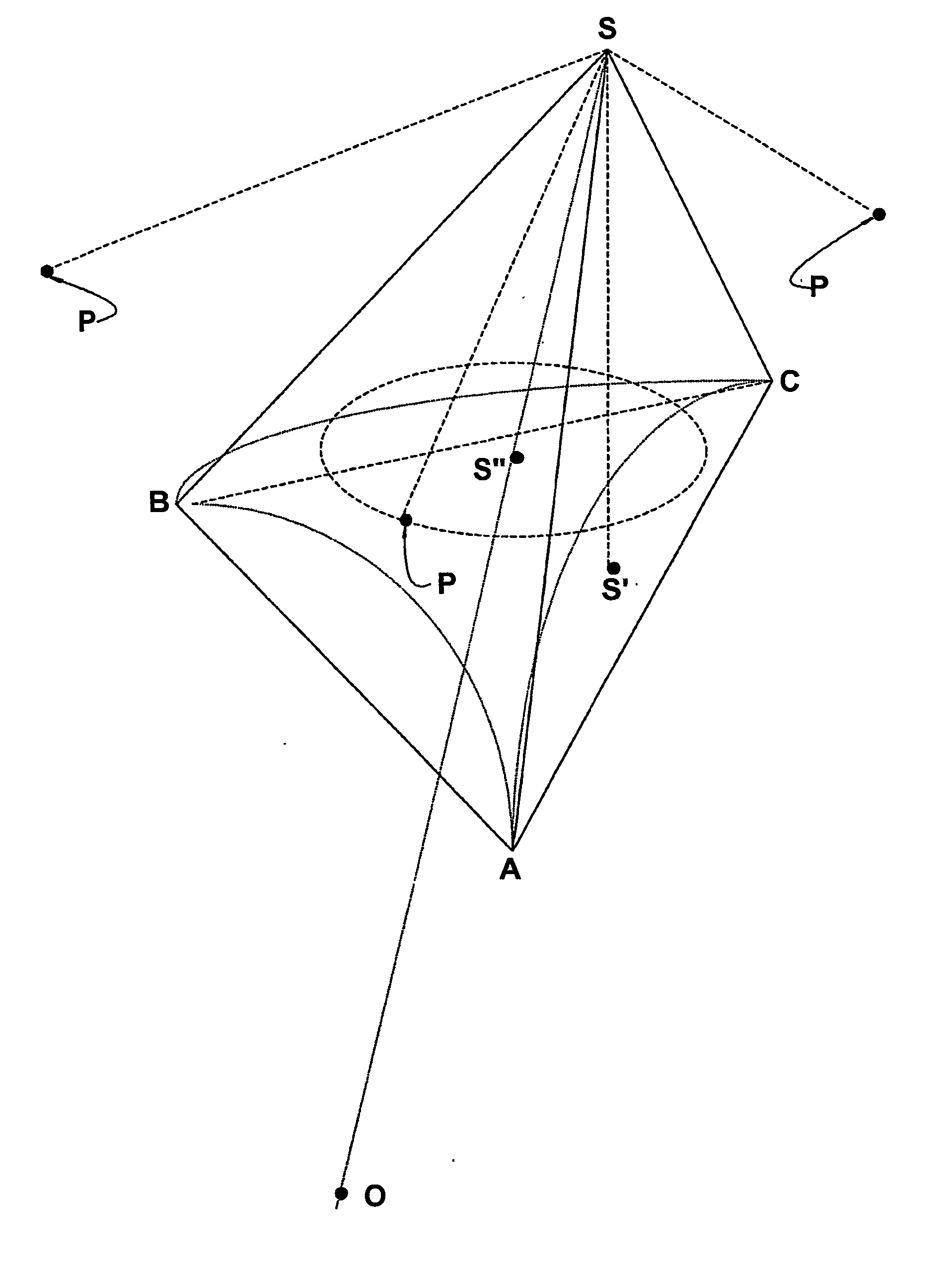
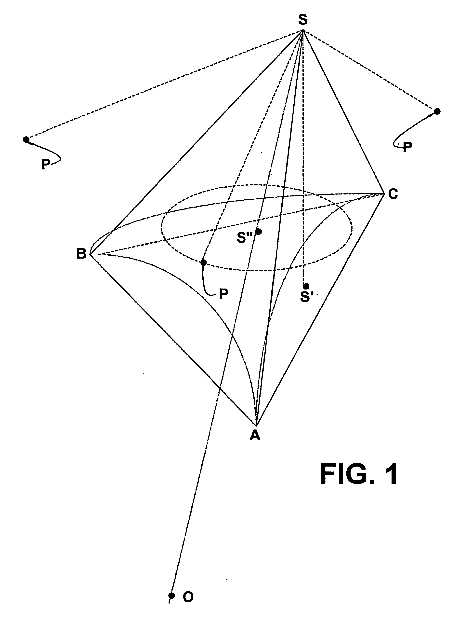
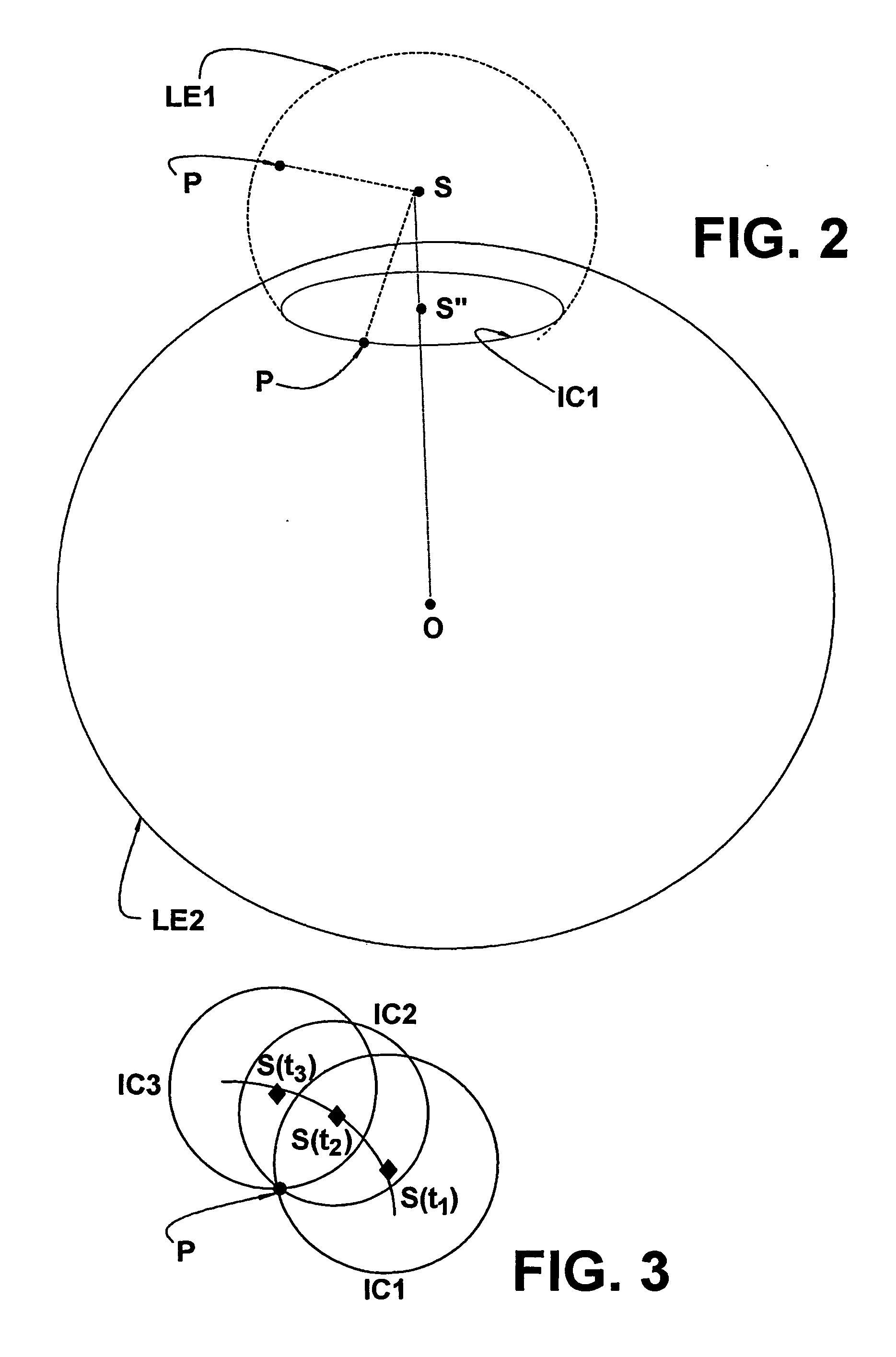
[0033] The results proposed by the present invention are obtained through a system constituted by at least three bases, which are fixed in relation to the earth and, for example, located on the surface thereof, namely, a first base A, a second base B, and a third base C, which are spaced away and disaligned in relation to each other and each having its respective geographic position well determined, said system further comprising: a space platform S, visible by said first, second and third fixed bases A, B, C and which moves to successive positions, as a function of time, according to a trajectory that is inclined in relation to the rotation axis of the earth; a transmitter 1 operatively associated with each of the parts defined by the first, the second and the third bases A, B, C and with the space platform S, in order to emit pulses in a determined frequency, each pulse in a predetermined reference instant; a receiver 2, operatively associated with each fixed base A, B, C and with...


PUM


Abstract

Geographical and space positioning system and process, comprising:a first, a second, and a third base (A, B, C) which are fixed in relation to the earth, but spaced away and disaligned in relation to each other, a space platform (S) which is visible from the fixed bases (A, B, C);at least one target (P) situated on or above the surface of the earth; a transnitter (1)operatively associated with each of the parts defined by the fixed bases (A, B, C) and the space platform (S) in order to emit pulses in a determined frequency, each pulse in a predetermined reference instant; a receiver (2)operatively associated with: each fixed base (A, B, C), each target (P) and with the transmitter (1) in order to receive said pulses in a trajectory covering the distance between the space platform (S) and the fixed base (A, b, C) associated with the receiver (2) a control unit (3) which is operatively connected to both the transmitter (1) and thereceiver (2) in order to calculate, for each pulse emission instant, the lateral edges of the tetrahedron, whose vetices are defined by the three fixed bases (A, B, C) and by the space platform (s), based upon the determination of the propagation time of each pulse in said trajectory , between the space platfom (S) and each fixed base (A, B, C), in order to allow determining a respectice extension of the trajectory of the space platform (S), while the latter is visible by the fixed bases (A, B, C) and determining, at the same time, its equation of motion, allowing calculating the possible positions of the target (P) in the control unit (3) and in the target (P) itself.

Description

FIELD OF THE INVENTION [0001] The present invention innovates in relation to other geographic and space positioning systems and processes in that it allows determining the position, the trajectory and the equation of motion of a platform situated in different and discrete locations in the space, for example an artificial satellite, and determining, at the same time, positions of targets situated on the ground or in space, based on the concept of the correlation between the time differences in the propagation of radio signals that are retransmitted by the space platform, by using geodesic reference bases on the surface of the earth. The invention dispenses any processings on board of the satellite, requiring simple detectors and processors in the targets, whose positioning is to be determined. The same space platform can eventually be used for data communication of the position of the targets. BACKGROUND OF THE INVENTION [0002] The systems and methods for determining the positions on...

Claims


Application Information

Patent Timeline
IPC IPC(8): G01S13/08G01S1/00G01S19/03G01S11/08G01S13/00G01S13/87G01S19/01G01S19/10G01S19/12G01S19/48H04L12/18
CPCG01S5/14G01S11/08G01S13/003G01S13/878G01S19/00
Inventor KAUFMANN, PIERRE
Owner KAUFMANN PIERRE
Why Eureka
Try Eureka