Moving picture coding method, and moving picture decoding method
Active Publication Date: 2007-02-22
PANASONIC INTELLECTUAL PROPERTY CORP OF AMERICA
View PDF25 Cites 86 Cited by
Summary
Abstract
Description
Claims
Application Information
AI Technical Summary
This helps you quickly interpret patents by identifying the three key elements:
Problems solved by technology
Method used
Benefits of technology
Benefits of technology
[0073] According to the present invention, in the above-described moving picture coding method, the picture position information is expressed with a shorter length code as the distance on the display time axis from the target picture to the already-coded B picture that is referred to in coding the target picture is shorter.
[0151] Further, in the present invention, there is provided a moving picture decoding method for decoding each of plural pictures constituting a moving picture to convert a bit stream corresponding to each picture into image data, which method includes a decoding step of decoding a target picture to be decoded with reference to an already-decoded picture, wherein a flag indicating whether or not the target picture should be used as a candidate for a reference picture when decoding another picture that follows the target picture, is described in the bit stream, and in the decoding step, management of the decoded target picture is carried out on the basis of the flag. Therefore, it is possible to correctly decode a bit stream corresponding to a B picture, which is generated by using, as forward reference pictures, a B picture subjected to bidirectional predictive coding as well as a P picture subjected to forward predictive coding.
Problems solved by technology
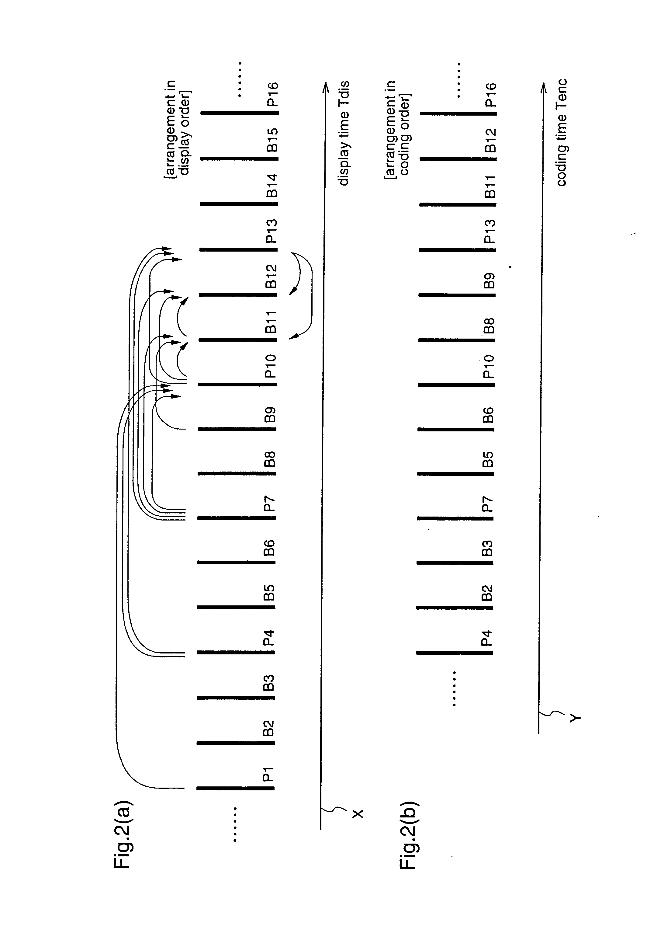
In this case, however, the reference index [1] assigned to the P picture P16 that is closer to the target picture (B picture B15) on the display time axis X becomes larger than the reference index [0] assigned to the P picture P19 that is far from the B picture B15, resulting in degradation of coding efficiency.
Method used
Image
Click on the blue label to locate the original text in one second.
Reading with bidirectional positioning of images and text.
Examples
embodiment 1
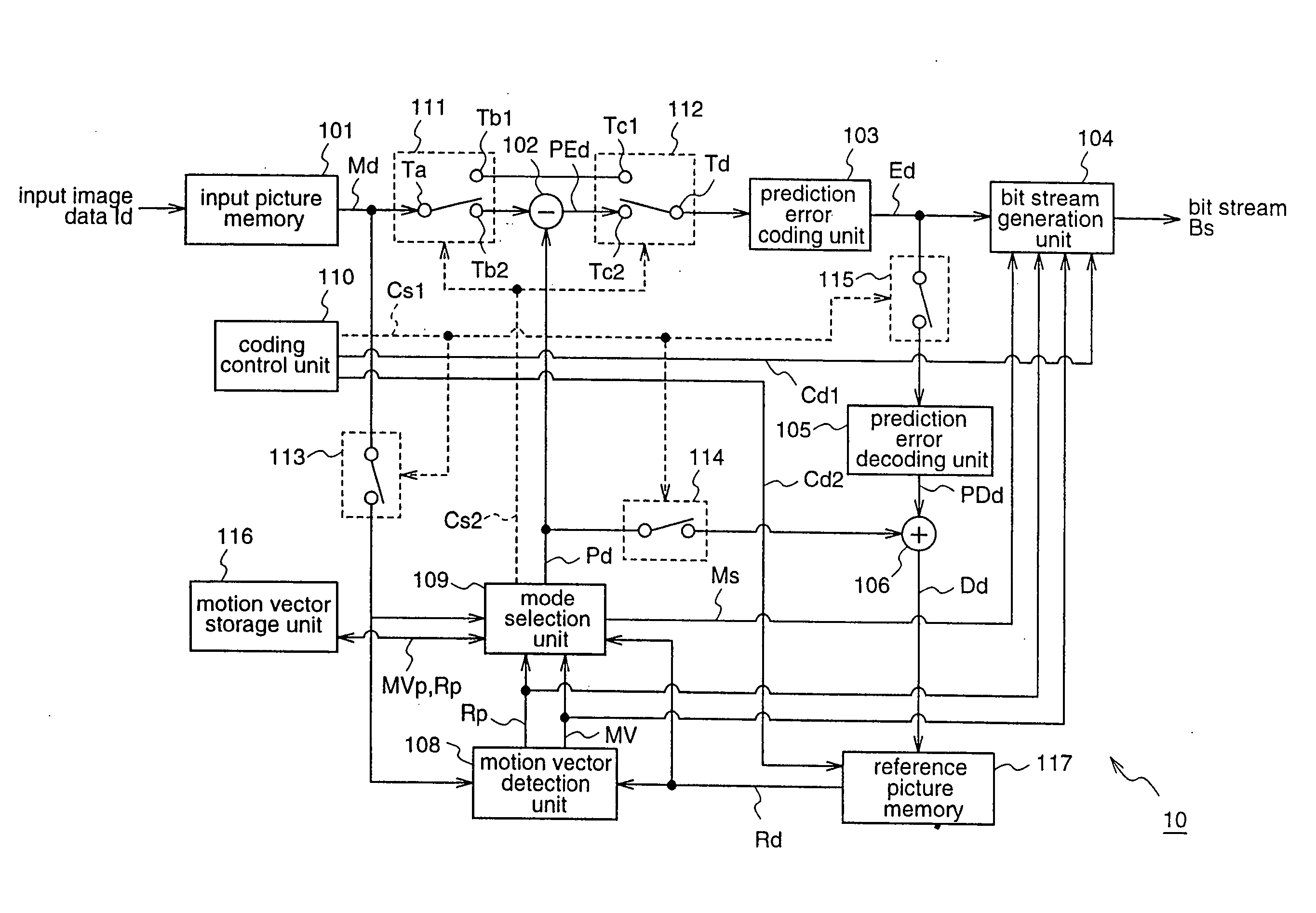
[0203]FIG. 1 is a block diagram for explaining a moving picture coding apparatus 10 according to a first embodiment of the present invention.
[0204] The moving picture coding apparatus 10 according to this first embodiment divides each of plural pictures constituting a moving picture into predetermined data processing units (blocks), and encodes image data of each picture for every block.
[0205] To be specific, the moving picture coding apparatus 10 includes an input picture memory (hereinafter also referred to as a frame memory) 101 for holding image data (input data) Id of inputted pictures, and outputting the stored data Id for every block; a difference calculation unit 102 for calculating difference data between image data Md of a target block to be coded, which is outputted from the frame memory 101, and prediction data Pd of the target block, as prediction error data PEd of the target block; and a prediction error coding unit 103 for compressively coding the image data Md of t...
embodiment 2
[0418] Hereinafter, a second embodiment of the present invention will be described.
[0419]FIG. 15 is a block diagram for explaining a moving picture decoding apparatus 20 according to a second embodiment of the present invention.
[0420] The moving picture decoding apparatus 20 decodes the bit stream Bs outputted from the moving picture coding apparatus 10 according to the first embodiment.
[0421] To be specific, the moving picture decoding apparatus 20 includes a bit stream analysis unit 201 for analyzing the bit stream Bs to extract various kinds of data; a prediction error decoding unit 202 for decoding coded data Ed outputted from the bit stream analysis unit 201 to output prediction error data PDd; and a mode decoding unit 223 for outputting a switch control signal Cs on the basis of mode information (coding mode) Ms relating to mode selection, which is extracted by the bit stream analysis unit 201.
[0422] The moving picture decoding apparatus 20 further includes a reference pic...
embodiment 3
[0569]FIG. 23 is a block diagram illustrating a moving picture coding apparatus 30 according to a third embodiment of the present invention.
[0570] The moving picture coding apparatus 30 can switch, according to a control signal supplied from the outside, a method for assigning reference picture indices to candidate pictures, between a method of assigning reference picture indices to candidate pictures according to an initialized rule (default assignment method), and an adaptive assignment method of assigning reference picture indices to candidate pictures by the default assignment method and, further, adaptively changing the assigned reference picture indices according to the coding status.
[0571] To be specific, one operation mode of the moving picture coding apparatus 30 according to the third embodiment is the operation of the moving picture coding apparatus 10 according to the first embodiment. In other words, when the default assignment method is selected as a reference pictur...
PUM
Abstract
According to the present invention, a moving picture coding apparatus (70) for performing inter-picture predictive coding for pictures constituting a moving picture is provided with a coding unit (103) for performing predictive error coding for image data; a decoding unit (105) for performing predictive error decoding for an output from the coding unit (103); a reference picture memory (117) for holding output data from the decoding unit (105); and a motion vector detection unit (108) for detecting motion vectors on the basis of the decoded image data stored in the memory. When coding a B picture as a target picture, information indicating whether or not the target picture should be used as a reference picture when coding another picture is added as header information. Therefore, in a decoding apparatus for decoding a bit stream Bs outputted from the moving picture coding apparatus (70), management of a memory for holding the reference picture can be facilitated on the basis of the header information.
Description
TECHNICAL FIELD [0001] The present invention relates to a moving picture coding method and a moving picture decoding method and, more particularly, to a method for coding or decoding pictures constituting a moving picture with reference to other pictures of the moving picture. BACKGROUND ART [0002] Generally, in coding of pictures constituting a moving picture, each picture is divided into plural blocks, and compressive coding (hereinafter, also referred to simply as “coding”) of image information possessed by each picture is carried out for every block, utilizing redundancies in the space direction and time direction of the moving picture. As a coding process utilizing redundancy in the space direction, there is intra-picture coding utilizing correlation of pixel values in a picture. As a coding process utilizing redundancy in the time direction, there is inter-picture predictive coding utilizing correlation of pixel values between pictures. The inter-picture predictive coding is a...
Claims
Application Information
Patent Timeline
Application Date:The date an application was filed.
Publication Date:The date a patent or application was officially published.
First Publication Date:The earliest publication date of a patent with the same application number.
Issue Date:Publication date of the patent grant document.
PCT Entry Date:The Entry date of PCT National Phase.
Estimated Expiry Date:The statutory expiry date of a patent right according to the Patent Law, and it is the longest term of protection that the patent right can achieve without the termination of the patent right due to other reasons(Term extension factor has been taken into account ).
Invalid Date:Actual expiry date is based on effective date or publication date of legal transaction data of invalid patent.

