
Electrical connector having a ground plane with independently configurable contacts

a ground plane, independent configurable technology, applied in the direction of connection contact material, coupling device connection, electrical apparatus, etc., can solve the problems of increasing the cost and difficulty of connector manufacturing, the pattern of shielded contacts cannot be easily customized, and the potential for problems, so as to achieve a simple and easily customizable construction

Inactive Publication Date: 2007-02-22
SAMTEC
View PDF31 Cites 17 Cited by
  • Summary
  • Abstract
  • Description
  • Claims
  • Application Information

AI Technical Summary

Benefits of technology

[0015] In order to overcome the problems described above, preferred embodiments of the present invention provide an electrical connector that has a relatively simple and easily customizable construction in which electrical disturbances such as EMI and crosstalk are minimized while also achieving impedance matching.
[0024] The step of forming the plurality of electrical contacts preferably includes forming the plurality of electrical contacts while the contacts are attached to a carrier strip, and eliminating a portion of the electrical contacts that define the signal contacts, preferably by cutting the arm portion of the contacts.

Problems solved by technology

As the number of electrical connections in a given volume increases, so does the potential for problems such as crosstalk between the connections.
Thus, this pattern of shielded contacts cannot be easily customized according to a specific application.
This greatly increases the cost and difficulty of connector manufacturing.
While the shielding configuration of this patent reduces crosstalk, it is difficult and expensive to mass produce connectors using the square-wave shaped shielding pieces, since it is difficult to maintain proper alignment of a large number shielding pieces having such a complex shape.
However, this arrangement also suffers from the problems described above.

Method used


Image

  • Electrical connector having a ground plane with independently configurable contacts
  • Electrical connector having a ground plane with independently configurable contacts
  • Electrical connector having a ground plane with independently configurable contacts

Examples


first embodiment

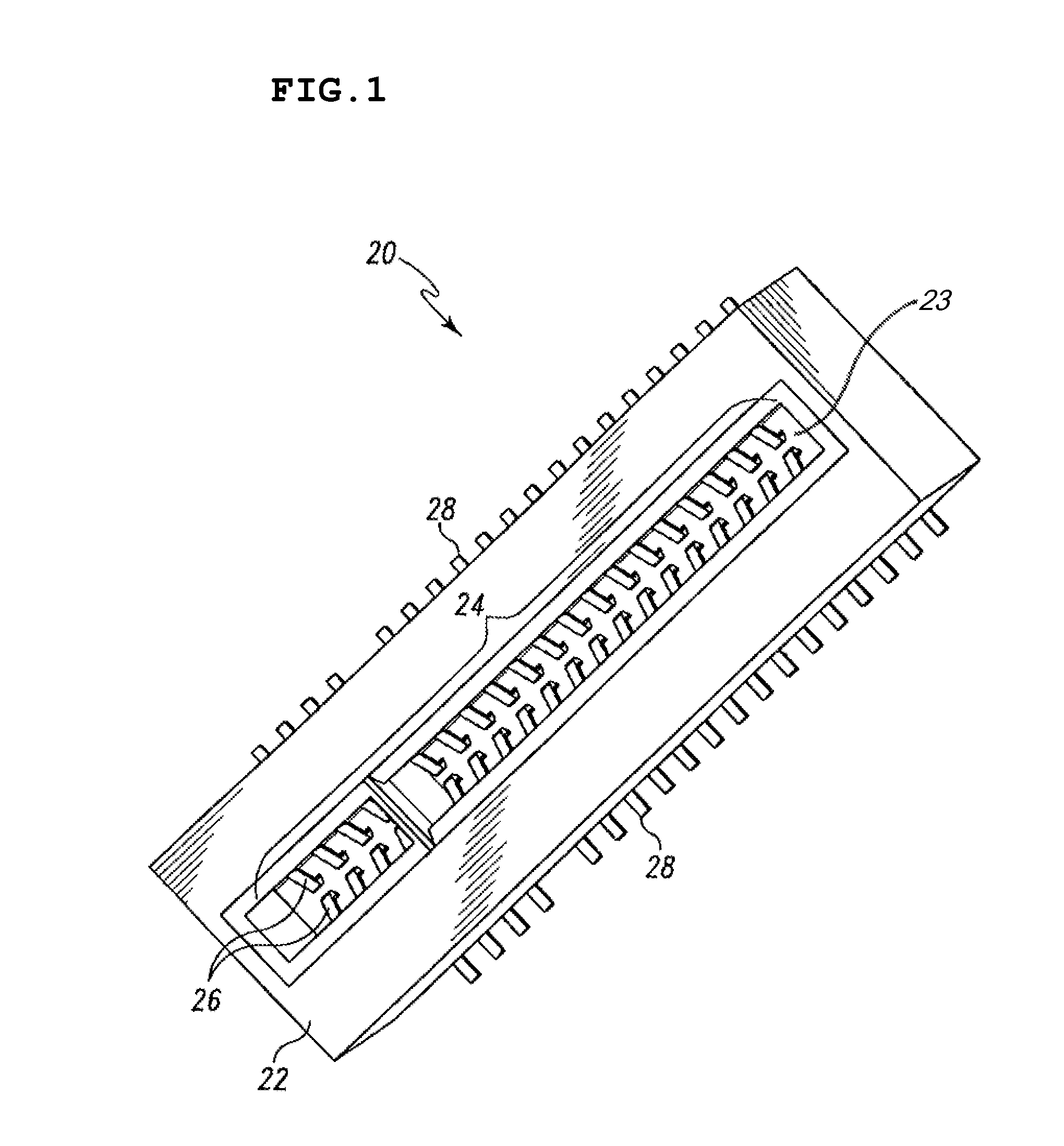
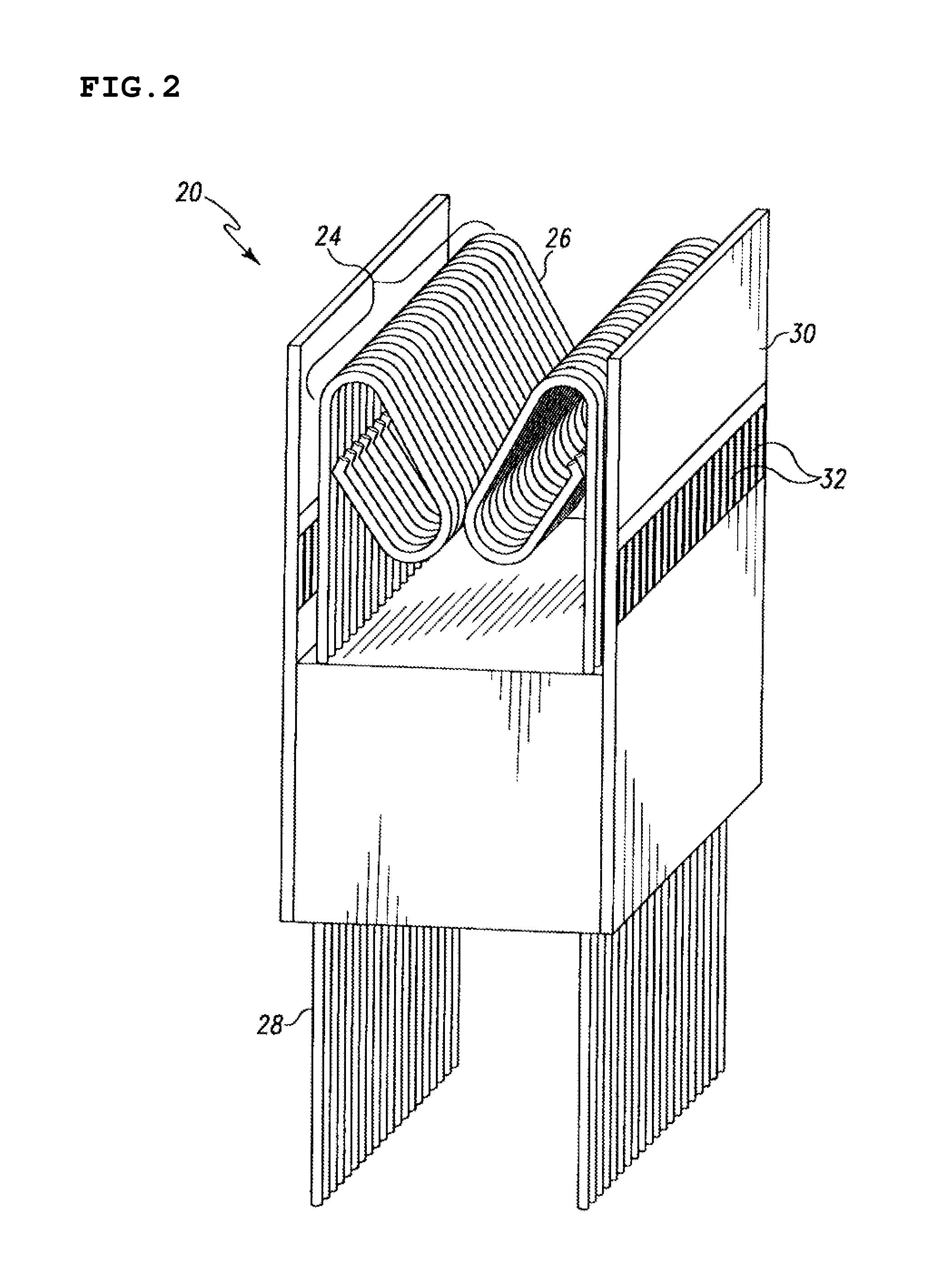
[0054]FIGS. 1-4A illustrate the present invention, an edge-type electrical connector 20 for receiving a plurality of electrical contacts and independently configurable to provide any desired pattern of grounding thereto. Referring to FIGS. 1-3, the electrical connector includes a housing portion 22 having a generally open top slot for receiving electrical contacts (generally conductive pads on the edge of a printed circuit board). The housing 22 further contains a plurality of electrical contact receptors or sockets 24 for receiving the individual electrical contacts and holding them in electric communication with a plurality of respective conductors 28. The plurality of electrical contact receptors 24 is generally arranged in a single row, although the plurality of electrical contact receptors 24 could be arranged in two or more parallel rows. As illustrated in FIG. 1, each electrical contact receptor 24 comprises a pair of elongated electrically conducting members 26 positioned op...

second embodiment

[0058]FIGS. 5-11 illustrate the present invention, a board-to-board type electrical connector 120 including a male connector assembly 121 and a female connector assembly 122 adapted to receive the male connector assembly 121 in electric communication. Both housing portions 121, 122 are adapted to receive electrical signals from an attached device. The female connector assembly 122 further includes a pair of independently configurable ground plates 30 adapted to provide any desired pattern of grounding thereto. The electrical connector includes a female connector assembly 122 having a generally open central slot 123 for receiving the compatible male connector assembly 121 in electrical communication. The central slot 123 further includes a plurality of electrical contact receptors 124 positioned therein. The male connector assembly 121 includes a plurality of sequentially disposed electric contacts 125. These electric contacts 125 are typically disposed as two rows, one on either elo...


PUM


Abstract

An electrical connector includes a housing, a plurality of contact pins, and at least one shield plane provided on the outside of the housing. Some of the contact pins are electrically connected to the at least one shield plane to define shield contact pins and some of the contact pins are not electrically connected to the at least one shield plane to define signal contact pins.

Description

[0001] This is a Continuation Application of U.S. patent application Ser. No. 10 / 879,901, filed Jun. 29, 2004, currently, which is a Continuation-in-Part Application of U.S. patent application Ser. No. 10 / 822,341, filed Apr. 12, 2004, now U.S. Pat. No. 7,121,849, which is a Divisional of U.S. patent application Ser. No. 09 / 863,960, filed May 23, 2001, now U.S. Pat. No. 6,739,884.BACKGROUND OF THE INVENTION [0002] 1. Field of the Invention [0003] The present invention generally relates to electrical connectors, and more particularly to an electrical connector having improved electrical characteristics including improved impedance matching, minimized crosstalk and significantly reduced emission and absorption of electromagnetic interference (“EMI”). [0004] 2. Description of the Related Art [0005] Electrical connectors are used to place electrical devices, such as printed circuit boards, in electrical communication with one another. Typically, an electrical connector includes a set of ...

Claims


Application Information

Patent Timeline
Patent Type & Authority Applications(United States)
IPC IPC(8): H01R13/648H01R12/16
CPCH01R12/57H01R13/6582H01R12/721H01R29/00
Inventor FERRY, JOSHUA L.VICICH, BRIAN R.FERRY, JULIAN J.
Owner SAMTEC
Learn More