Method of assembling a graphical image biomechanical supplement

Inactive Publication Date: 2007-02-22
BECKER THEODORE J
31 Cites 0 Cited by

AI-Extracted Technical Summary

Problems solved by technology

Typical administrative summary forms relating to employee's physical capacities are generally limited to written descriptions of the employees of physical capacities.
When presented in a form, it is often difficult for a physician to differentiate what a normal healthy person of similar age, sex, education, and body build would be capable of doing.
However, these forms again do not have the option for selecting a body posture or position or body part position by graphic image and thus re...

Method used

[0061] The biomechanical images and FIGS. 1A-1AC are grouped in the electronic database and grouped for display into main categories and subcategories for the purpose of categorizing similar postures and body positions for easier identification purposes. For example, FIGS. 1A-1C are grouped in the main category of “hand repetition/grasp,” with FIG. 1A's subcategory of “fine hand grasp,”FIG. 1B's subcategory of “gross hand grasp,” and FIG. 1C's subcategory of “dryer hand grasp.” FIGS. 1A-1AC depict a universal and comprehensive library or database of biomechanical images not groupe...

Benefits of technology

[0007] Rather than relying on the merits of the injured worker's subjective input in determining return to work, increasingly physicians have recognized the need for objective physical findings. The cha...

Abstract

The method of assembling a graphical image biomechanical supplement invention involves assembling a plurality of biomechanical images selected from an electronic database onto a single document, wherein the biomechanical images are line art silhouettes representing human body postures or positions and specific body part positions. The method of assembling includes selecting at least two biomechanical images from a plurality of biomechanical images, assigning a supplemental description to each of the selected at least two biomechanical images, and compiling the selected at least two biomechanical images and their assigned supplemental descriptions onto a single document. Each of the plurality of biomechanical images may include a brief text description. The selection of biomechanical images may be from a universal biomechanical image database that includes every selectable biomechanical image, or a work specific biomechanical image grouping compiled from a universal biomechanical image database.

Application Domain

Physical therapies and activitiesLigaments +6

Technology Topic

Paper documentImage database +7

Image

  • Method of assembling a graphical image biomechanical supplement
  • Method of assembling a graphical image biomechanical supplement
  • Method of assembling a graphical image biomechanical supplement

Examples

  • Experimental program(1)

Example

[0057] Similar reference characters denote corresponding features consistently throughout the attached drawings.
DETAILED DESCRIPTION OF THE PREFERRED EMBODIMENTS
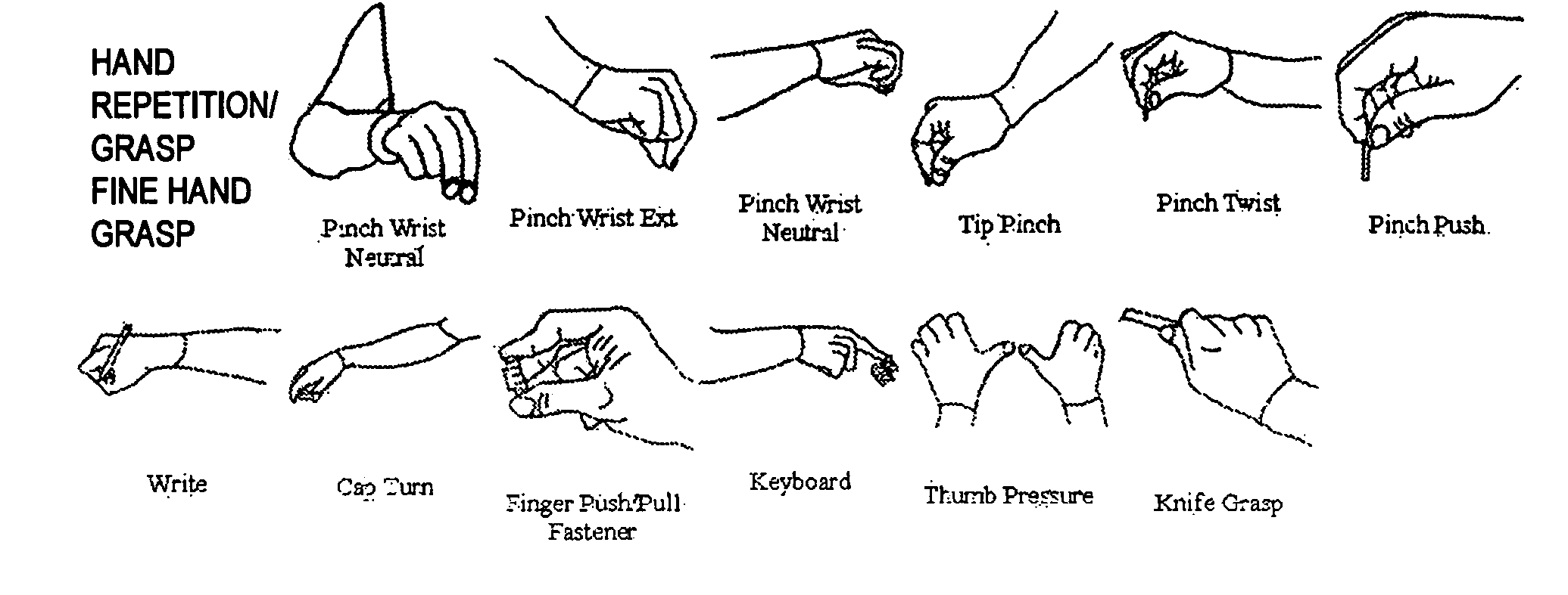
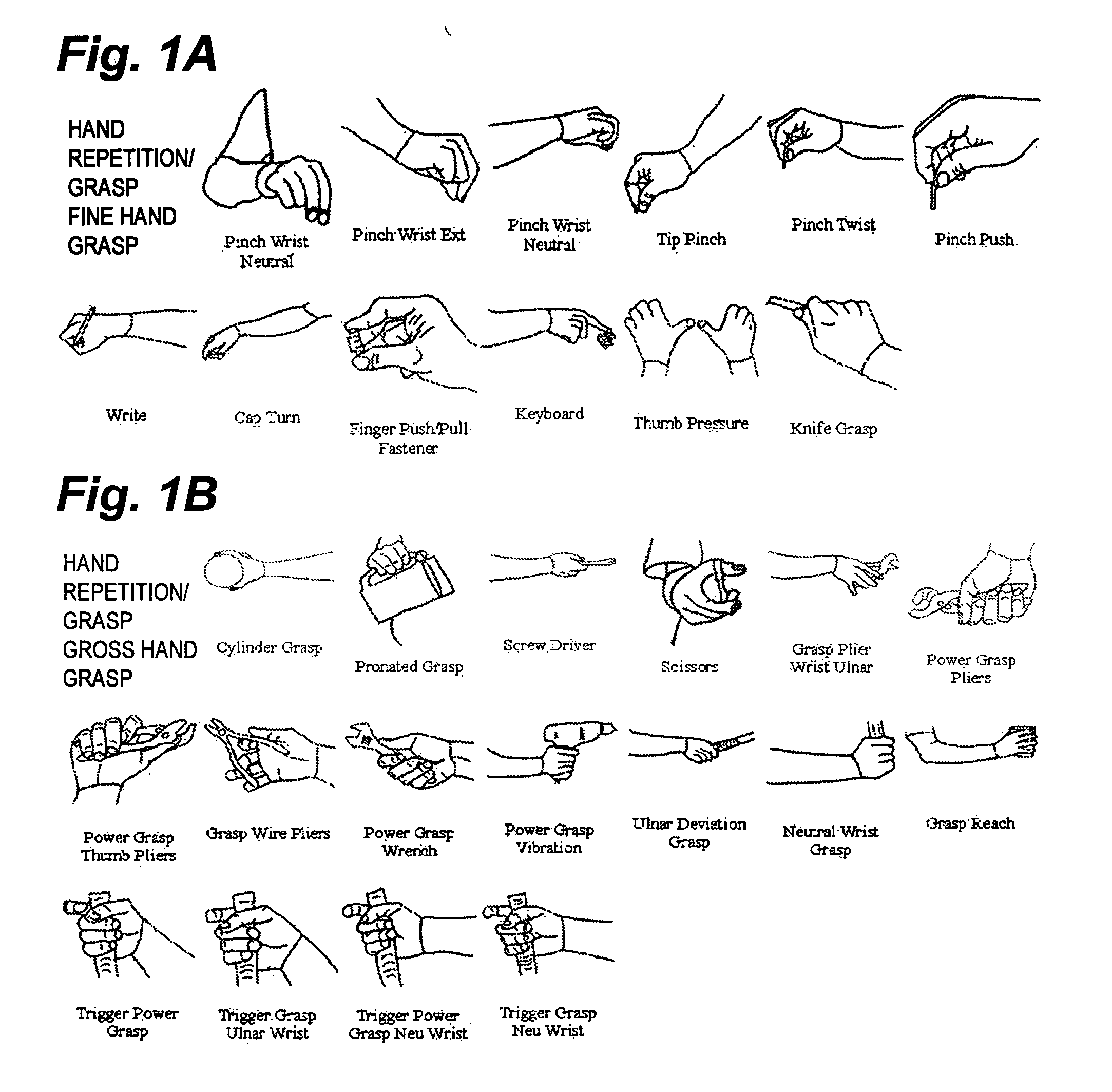
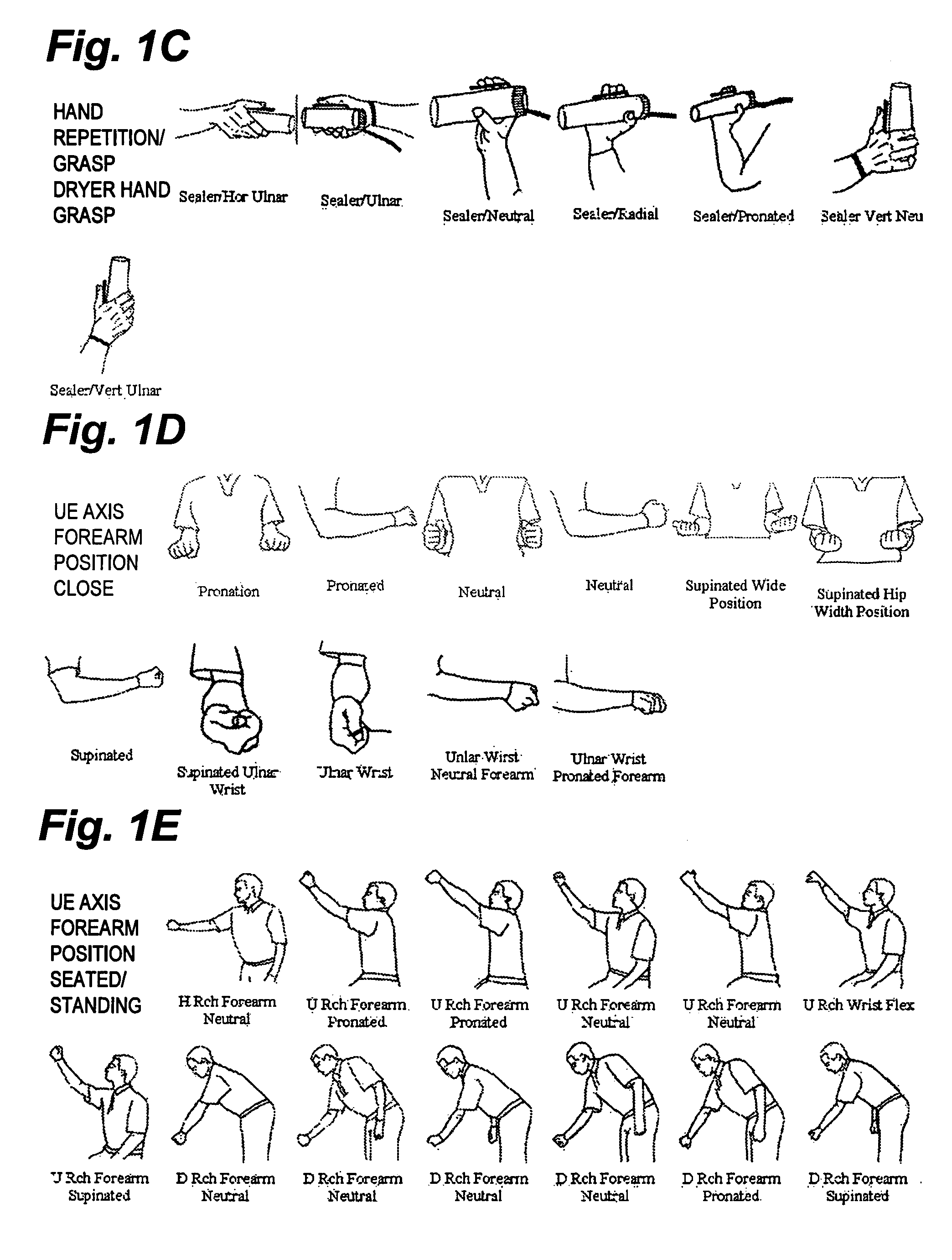
[0058] The method of the present invention is directed toward assembling under computer control a number of biomechanical images onto a single document. This single document, called hereinafter a biomechanical supplement, provides a summary of graphical images representing body postures or positions and body part positions associated with a particular job function or work environment. The biomechanical supplemental is intended to be an attachment to a job analysis used by employers, vocational counselors, insurers, physicians, attorneys, occupational therapist, physical therapist, and users of function capacity evaluations for evaluating a potential employee's capacity to perform a job, disability claims, insurance premiums, etc.
[0059] The first step in generating the biomechanical supplement includes selecting biomechanical images from a biomechanical image database stored in a computer readable format for retrieval by a computer. The biomechanical image database represented in FIGS. 1A-1AC includes line art silhouettes representing human body postures or positions and specific body part positions. Each biomechanical image includes a brief text description of the body posture/position or body part position represented in the image. The biomechanical image database can be continually updated with images representing any type of new work posture or position information related to specific industries, work environments or job requirements.
[0060] These biomechanical images may be stored in a computer readable database as electronic image files or in a hard-copy printed format. The method of selecting the biomechanical images can easily be accomplished through the use of a graphical user interface device (GUI) on that of a computer, personal digital assistant (PDA), or an interactive communication device such as a cell phone with a capable display. All of these devices have a graphical display and a processor capable of retrieving, arranging, storing and outputting for display or for printing the biomechanical images.
[0061] The biomechanical images and FIGS. 1A-1AC are grouped in the electronic database and grouped for display into main categories and subcategories for the purpose of categorizing similar postures and body positions for easier identification purposes. For example, FIGS. 1A-1C are grouped in the main category of “hand repetition/grasp,” with FIG. 1A's subcategory of “fine hand grasp,”FIG. 1B's subcategory of “gross hand grasp,” and FIG. 1C's subcategory of “dryer hand grasp.” FIGS. 1A-1AC depict a universal and comprehensive library or database of biomechanical images not grouped by any specific type of work, but grouped only by similar postures and body positions.
[0062] A person selecting biomechanical images from such a universal and comprehensive library or database would need to identify specific biomechanical images associated with a particular job or work function.
[0063] For ease of selecting biomechanical images, an alternative to searching a universal database of biomechanical images would be to search a pre-grouped database of biomechanical images organized by a specific job or work environment. Such is the example of FIGS. 2A-2F wherein biomechanical images are grouped into a representative category of “office” work and are then subcategorized into similar body postures or positions and body positions related to tasks associated with the office environment.
[0064] The pre-grouped biomechanical images taken from the universal biomechanical image database may be grouped by any relevant criterion. For example, biomechanical images may be pre-compiled prior to selection based on all varieties of a single titled (main category or subcategory) body posture or position or body part position, body postures or positions or body part positions associated with a particular type of job or work environment, the particular stature of a worker in any particular environment, for a particular type of equipment used on a job or a company's policy with respect to a particular type of equipment used on a job, or body postures or positions or body part positions associated with seasonal changes affecting a job.
[0065] After the biomechanical images have been selected from either the universal database or a pre-compiled sub-grouping of biomechanical images, a supplemental description may be assigned to each selected biomechanical image. The supplemental description may include information regarding the frequency of operation associated with the biomechanical image, for example how often the posture or position is used on a specific job or work environment. Additionally, a time period, a load or weight, or a minimum requirement or special requirement associated with the body posture or position or position of the biomechanical image may be assigned as the supplemental description.
[0066] The assignment of the supplemental description for a particular biomechanical image may be accomplished in two ways. The first being a free form field wherein a user may input a supplemental description of their own choosing to be associated with the biomechanical image. This may be accomplished by typing via a computer or other text input-enabled device or manually writing the supplemental description with the biomechanical image in a printed format.
[0067] The second method for assigning a supplemental description may be the selection of one or more supplemental descriptions from a predetermined list of items. If the assigning of a supplemental description is taking place on an electronic device with a graphical user interface (GUI), a selectable menu may offer the user a list of supplemental descriptions to choose from to associate with a particular biomechanical image. Alternatively, a user may manually choose from a list of supplemental descriptions by identifying their selection of a choice of supplemental descriptions on a printed form that contains the biomechanical image. Supplement descriptions in this alternative may be symbols associated with a common legend capable of being identified and selected by the user.
[0068] The final step in assembling the biomechanical images onto the biomechanical supplement document includes organizing or grouping the biomechanical images into similar body posture or position or body part position categories within the document itself. This grouping and identification allows for clear and rapid communication and understanding of the job function capacities based on the grouped biomechanical images.
[0069] The completed biomechanical supplement document may then take the form of a printed document, a printed placard or sign, an electronic document including the biomechanical images and supplemental descriptions, an electronic image of a computer-generated or printed documents, or a database record having searchable image and text fields of data.
[0070] The printed form of the biomechanical supplement may be printed by a computer controlled printing device to paper media, rigid or board-type media, transparent projection media, or any media suitable for printed publication or graphical communication. The computer controlled printing device may include a computer where a user selects biomechanical images from an electronic image database, the computer then arranges the selected images by type of body posture/position and body part position, and allows the user to input supplemental descriptions to each of the images. Additionally, the computer controlled printing device may include a printer for printing the biomechanical supplement including the selected and organized images and their corresponding supplemental description information.
[0071] Likewise, a computer readable medium may store the information of the fully compiled biomechanical supplement and may include an electronic document, such as a word processing file or an cross-platform electronic document (such as an Adobe(R) Portable Document File—PDF), an electronic image of a computer generated or a printed document, such as any type of graphic image file (TIFF, bitmap, JPEG, etc.), a database record capable of storing graphic image data or linking to graphic image database records, or any computer readable medium suitable for storing and presenting a graphical image.
[0072]FIG. 3A illustrates a blank biomechanical supplement form 10. A header section 11 includes data fields for identifying a worker, claim number and other relevant case specific information. A special note section 13 includes space for the writer to input additional information as necessary. Reference number 15 indicates the area where the biomechanical images will be placed on the form 10. Below that area is a table 17 for the supplemental description and further notes. For example, the first field in the table for each biomechanical image designates “Time Tol.” for time tolerance to indicate the period of frequency associated with the specific biomechanical image. Underneath, a “Job Match” field may be used to designate whether or not an employee is matched for the function indicated in the associated biomechanical image. These table field designations are for illustration purposes only and are not to be taken as limiting the scope of the present invention to only these types of data. As described above, supplemental description data may be any data that the user deems important and relevant to the biomechanical image associated with it. Reference number 19 illustrates the capacity of the biomechanical supplement to include multiple sections of biomechanical images and supplemental descriptions.
[0073]FIG. 3B illustrates a biomechanical supplement 20 similar to FIG. 3A. The header section 21, and special notes section 25 remain the same as the previous FIG. 3A. However, a legend 23 illustrates certain characters associated with a frequency of operation, i.e., S=Seldom performed; L=Limited performance; O=Occasionally performed; F=Frequently performed; and, C=Continuously preformed. Reference number 27 designates the area where the biomechanical images are placed. Reference number 29 designates a table where supplemental descriptions can be identified based on characters associated with the legend 23 above. Reference number 31 again illustrates the capacity of the biomechanical supplement to include multiple sections of biomechanical images and supplemental descriptions chosen from a pre-selected list of descriptions.
[0074]FIG. 4A illustrates a biomechanical supplement 40 including biomechanical images at the section illustrated by reference number 45 but with a blank supplemental description table 47 capable of being filled in by a user. The header information 41 and special note section 43 are identical to the previously identified biomechanical supplements. However, the section represented by reference number 45 now indicates a category description for the biomechanical images on the upper left corner of the supplemental description table. For example, the text “Hand Repetition/Hand Grasp” identifies the following six biomechanical images as being part of that specific biomechanical category. The section represented by reference number 49 illustrates two different distinctive biomechanical categories and their respective biomechanical images.
[0075]FIG. 4B illustrates a biomechanical supplement 50 including biomechanical images at 57 now including a supplemental description table 59 associated with a predetermined list of descriptions identified by the legend at 53. Again, the header information 51 and special note section 55 are identical to the previously identified biomechanical supplements. As in FIG. 4A, the section represented by reference number 57 now indicates a category description for the biomechanical images on the upper left corner of the supplemental description table. The section represented by reference number 61 now illustrates two distinctive biomechanical categories, their respective biomechanical images and the predetermined choices for the user to choose their supplemental descriptions.
[0076] The disclosed invention of the biomechanical supplement is designed to accurately and quickly convey information to healthcare providers, employers, prospective employees, administrative agencies, triers of fact, etc., regarding a worker's physical capacity, particular job requirements, a forensic tool to identify a person's lack of capacity due to workplace injury, or any other situation where both a quantitative and qualitative description of physical capacity or incapacity is needed.
[0077] It is to be understood that the present invention is not limited to the embodiments described above, but encompasses any and all embodiments within the scope of the following claims.

PUM

no PUM

Description & Claims & Application Information

We can also present the details of the Description, Claims and Application information to help users get a comprehensive understanding of the technical details of the patent, such as background art, summary of invention, brief description of drawings, description of embodiments, and other original content. On the other hand, users can also determine the specific scope of protection of the technology through the list of claims; as well as understand the changes in the life cycle of the technology with the presentation of the patent timeline. Login to view more.
Why Eureka
Try Eureka