Needle for stereographic embroidery

Inactive Publication Date: 2007-03-01
YANG CHIH PO
View PDF16 Cites 7 Cited by
  • Summary
  • Abstract
  • Description
  • Claims
  • Application Information

AI Technical Summary

Benefits of technology

[0010] 2. The drilling circumference can squeeze outwards the yarns around it to provide a good basis for embroidering, able to obtain a more stereographic and aesthe

Problems solved by technology

Because the arêtes 22 is rather sharp, they may cut off the longitudinal and the latitudinal yarns of the cloth while drilling through the cloth for embroidering, causing damage to the structure of the cloth losing its

Method used


Image

  • Needle for stereographic embroidery
  • Needle for stereographic embroidery
  • Needle for stereographic embroidery

Examples


Example

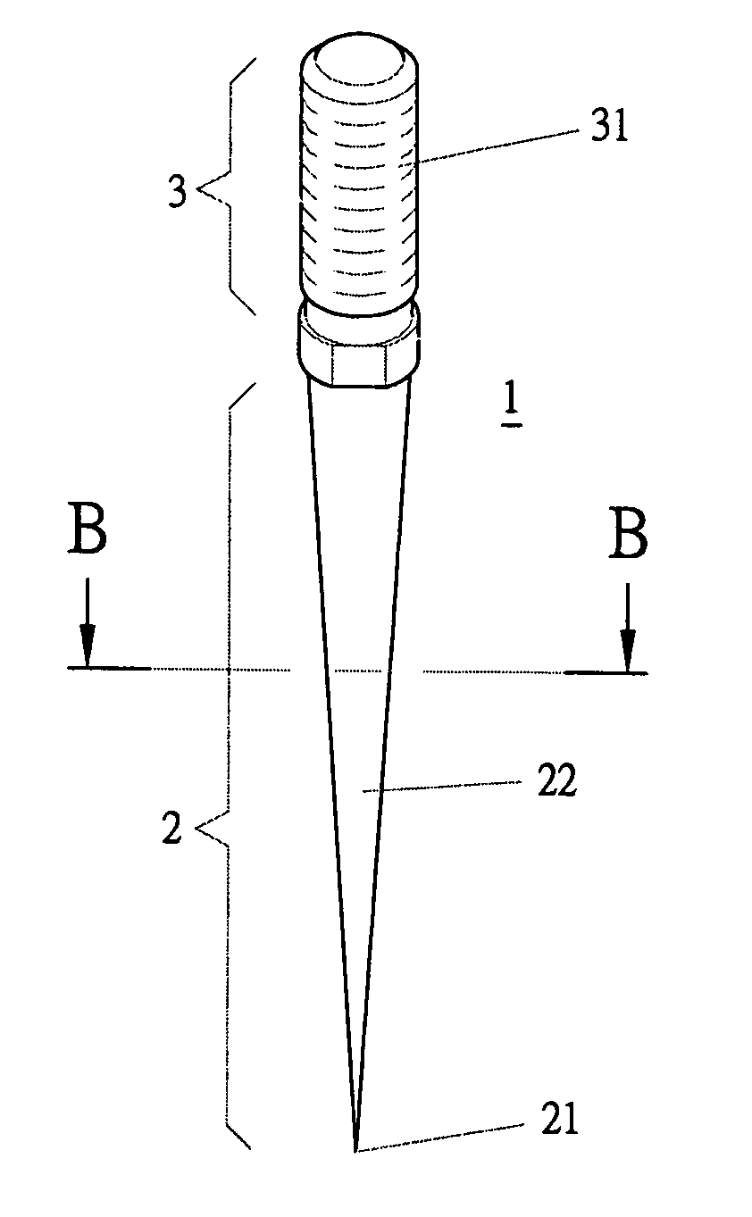
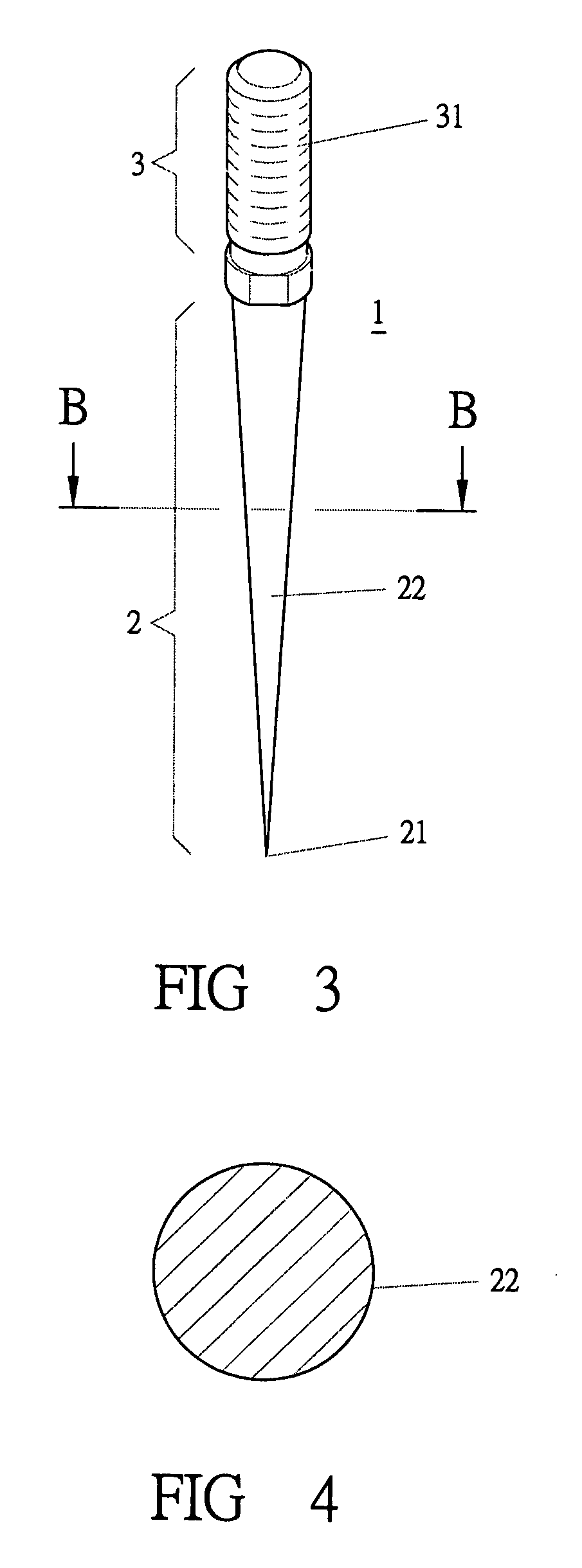
[0022] As shown in FIGS. 3 and 4, a preferred embodiment of a needle for stereographic embroidery in the present invention is mainly composed of a main body 1 which is provided with a tapered drilling part 2 and a fixing pivot 3. The fixing pivot 3 is provided with a thread 31 to screw with an embroidering machine. The tapered drilling part 2 is shaped as a smooth cone having a drilling tip 21 and a drilling circumference 22.

[0023] In using, when the needle in the invention is to drill through a cloth 4, the drilling tip 21 will first pass through a hole 41 in the cloth 4 and, then, the 22 is to squeeze yarns 42 as shown in FIG. 5, making the yarns 42 become denser. Next, while the needle in the invention moves away from the cloth 4, the hole 41 is kept as shown in FIG. 6. By the same time, a wanted picture can be embroidered on the denser yarns 42, which will make the embroidered picture be more vivid and stereographic.

[0024] Furthermore, the tapered drilling part 2 is not merely...


PUM


Abstract

A needle for stereographic embroidery is mainly composed of a main body which is provided with a tapered drilling part, shaped as a cone for drilling through a cloth easily, and a fixing pivot, at its other side, having a thread for screwing together with a embroidering machine. The tapered drilling part, being shaped as a cone, can drill through a hole of the cloth to squeeze outwards the longitudinal and the latitudinal yarns around the hole without damaging to them, achieving the previous drilling action in the stereographic embroidery and keeping the cloth as a whole. Because the drilling action does not damage to any yarns but squeezes them outwards, it provides a more complete basis for embroidering on the yarns to obtain a more vivid and stereographic picture.

Description

BACKGROUND OF THE INVENTION [0001] 1. Field of the Invention [0002] This invention relates to a needle for stereographic embroidery, particularly to one that carries out the previous drilling work without breaking down yarns of a cloth to keep the cloth as a whole, enabling the needle to avoid the defects, breaking down the yarns and reducing the strength of the cloth, the conventional has. Since the drilling action in the present invention does not damage the cloth as the conventional does, it provides a more complete basis for embroidering on the yarns with a more vivid and stereographic picture. And, due to a drilling circumference of a tapered drilling part is shaped as a cone, it is to endure an even force, reducing abrasion greatly. [0003] 2. Description of the Prior Art [0004] A conventional needle for embroidering, as shown in FIGS. 1 and 2, is mainly composed of a main body 1 provided with a tapered drilling part 2 and a fixing pivot 3. The tapered drilling part 2 is formed...

Claims


Application Information

Patent Timeline
IPC IPC(8): D05B85/00
CPCD05C11/02
Inventor YANG, CHIH-PO
Owner YANG CHIH PO
Why Eureka
Try Eureka