Apparatus for machine tool feedrate override using limiting parameters corresponding to actual spindle speed

Active Publication Date: 2007-03-01
THE BOEING CO
View PDF6 Cites 28 Cited by
  • Summary
  • Abstract
  • Description
  • Claims
  • Application Information

AI Technical Summary

Benefits of technology

[0011] The processing device may adjust the feedrate of the machine tool by adjusting a feedrate override value. The processing device may further adjust the feedrate override value based on a user-selected feedrate override value. In one embodiment, the processing device adjusts,the feedrate of the machine tool by outputting a feedrate override value to a computer numeric control that is controlling the machine tool.
[0012] The processing device may reduce the feedrate of the machine tool if the current spindle value is greater than the respective spindle parameter limit and may increase the feedrate of the machine tool if the current spindle value is less than the respective spindle parameter limit. Alternatively, the processing device may increase the feedrate if the feedrate is less than a predefined maximum feedrate.
[0013] In one embodiment, the plurality of spindle parameter limits is a first plurality of spindle parameter limits, the plurality of corresponding spindle rotational speeds is a first plurality of corresponding spindle rotational speeds and the current spindle value is a first current spindle value. The spindle parameter data may comprise a second plurality of spindle parameter limits and a second plurality of corresponding spindle rotatio

Problems solved by technology

Circumstances may exist where the movement of the workpiece relative to the cutting tool at the programmed feedrate while the workpiece is being milled produces excessive torque and/or excessive radial loading.
A

Method used


Image

  • Apparatus for machine tool feedrate override using limiting parameters corresponding to actual spindle speed
  • Apparatus for machine tool feedrate override using limiting parameters corresponding to actual spindle speed
  • Apparatus for machine tool feedrate override using limiting parameters corresponding to actual spindle speed

Examples


Example

[0023] Embodiments of the invention now will be described more fully hereinafter with reference to the accompanying drawings, in which some, but not all embodiments of the inventions are shown. Indeed, these inventions may be embodied in many different forms and should not be construed as limited to the embodiments set forth herein; rather, these embodiments are provided so that this disclosure will satisfy applicable legal requirements. Like numbers refer to like elements throughout.

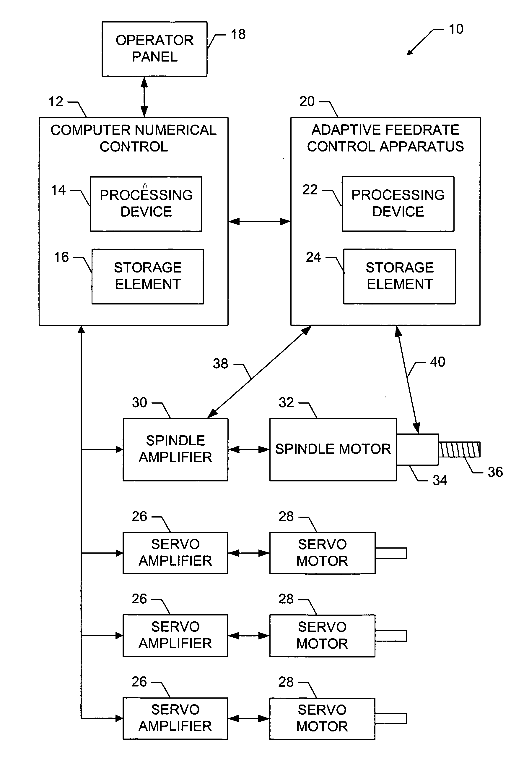
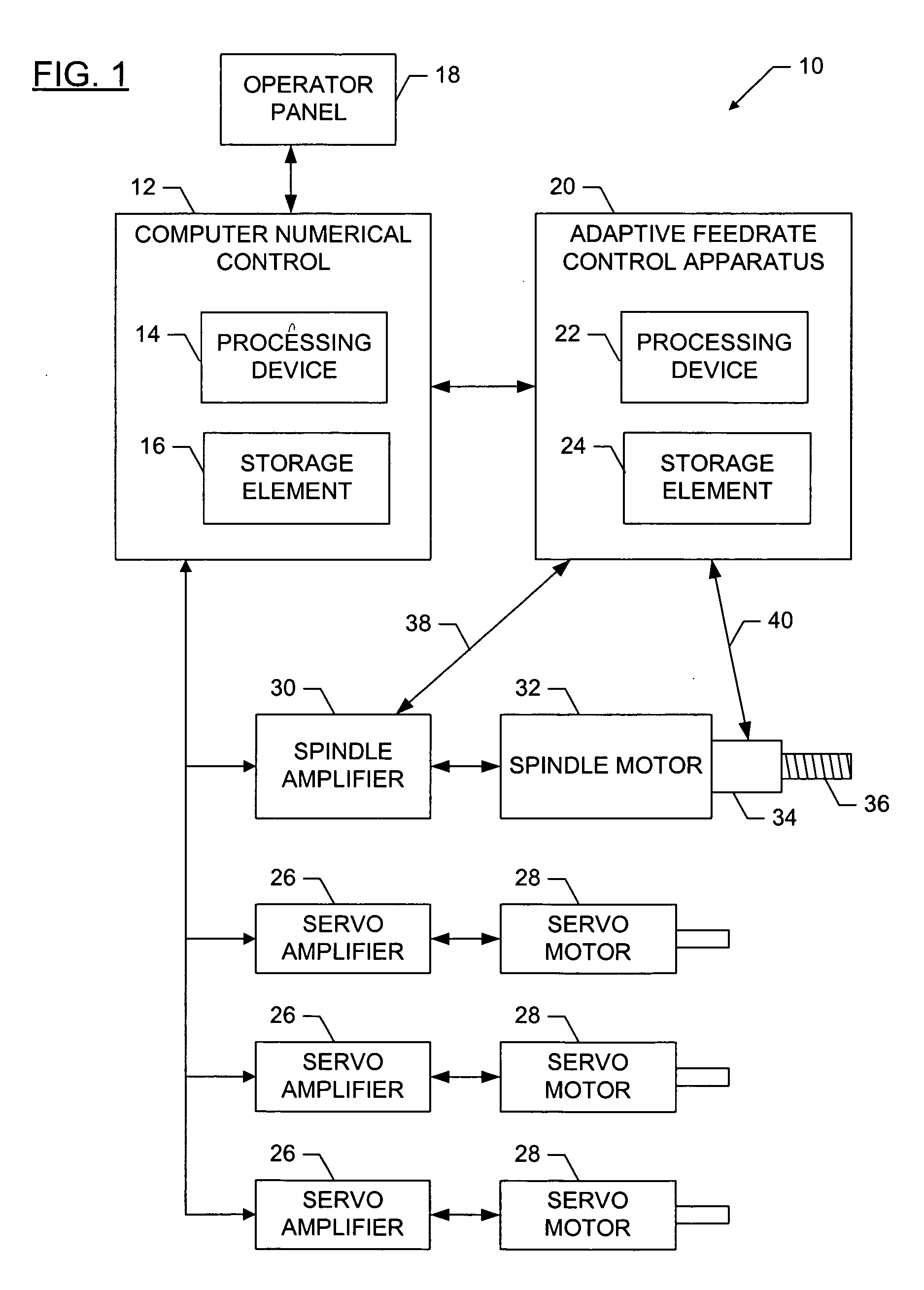
[0024]FIG. 1 is a functional block diagram of a system 10 for providing adaptive control of the feedrate of a machine tool, according to one embodiment of the invention. The system may comprise an adaptive feedrate control apparatus 20, in turn comprising a processing device 22 and a storage element 24. The processing device 22 could be, for example, a computing device, central processing unit, processor, controller, programmable gate array, or some other device that processes data. The system may furt...


PUM


Abstract

An apparatus, machine tool, and method for adaptively controlling a feedrate of a machine tool are provided in which a plurality of maximum spindle power and/or radial load values, each corresponding to a spindle rotational speed, are received, stored and applied. Additionally, the current spindle power and/or the current radial load, along with the current spindle rotational speed may be received. The current spindle power and/or the current radial load may be compared to the maximum spindle power and/or radial load corresponding to the current spindle rotational speed, such that the feedrate may be reduced if the current spindle power and/or the current radial load exceed the corresponding maximum spindle power and/or radial load for the current spindle rotational speed or increased if the current spindle power and the current radial load are below the corresponding maximum spindle power and/or radial load for the current spindle rotational speed.

Description

FIELD OF THE INVENTION [0001] The present invention relates generally to controls for machine tools, and more particularly, to an apparatus capable of controlling the feedrate override of a machine tool using limiting parameters corresponding to actual spindle speed. BACKGROUND OF THE INVENTION [0002] Machine tools are material cutting machines that are used in the manufacturing process for many different products. There are many types of machine tools, such as milling machines, lathes, and grinding machines. A milling machine is typically used to cut (i.e., mill) a desired shape into a raw piece of material (termed a workpiece). A milling machine typically comprises a movable table to which the workpiece is affixed. The table is typically capable of moving in two perpendicular directions, and the two different directions are typically termed the X-axis and the Y-axis. The table is typically connected to one or more devices (e.g., leadscrews) capable of translating the shaft rotatio...

Claims


Application Information

Patent Timeline
IPC IPC(8): G05B19/25
CPCG05B19/4163G05B2219/49108G05B2219/49092G05B2219/43158
Inventor XU, LIANGJI
Owner THE BOEING CO
Why Eureka
Try Eureka