Glow stick holder

a technology of a glow stick and a mounting bracket, which is applied in the field of mounting brackets, can solve the problems of no bracket device in the related art specifically adaptable, limited use of glow sticks, etc., and achieves the effects of convenient removal and replacement, convenient mounting, and convenient mounting

a technology of a glow stick and a mounting bracket, which is applied in the field of mounting brackets, can solve the problems of no bracket device in the related art specifically adaptable, limited use of glow sticks, etc., and achieves the effects of convenient removal and replacement, convenient mounting, and convenient mounting

US20070047216A1Inactive Publication Date: 2007-03-01PIAZZOLLA PAUL

Image

  • Glow stick holder
  • Glow stick holder
  • Glow stick holder

Examples


Embodiment Construction

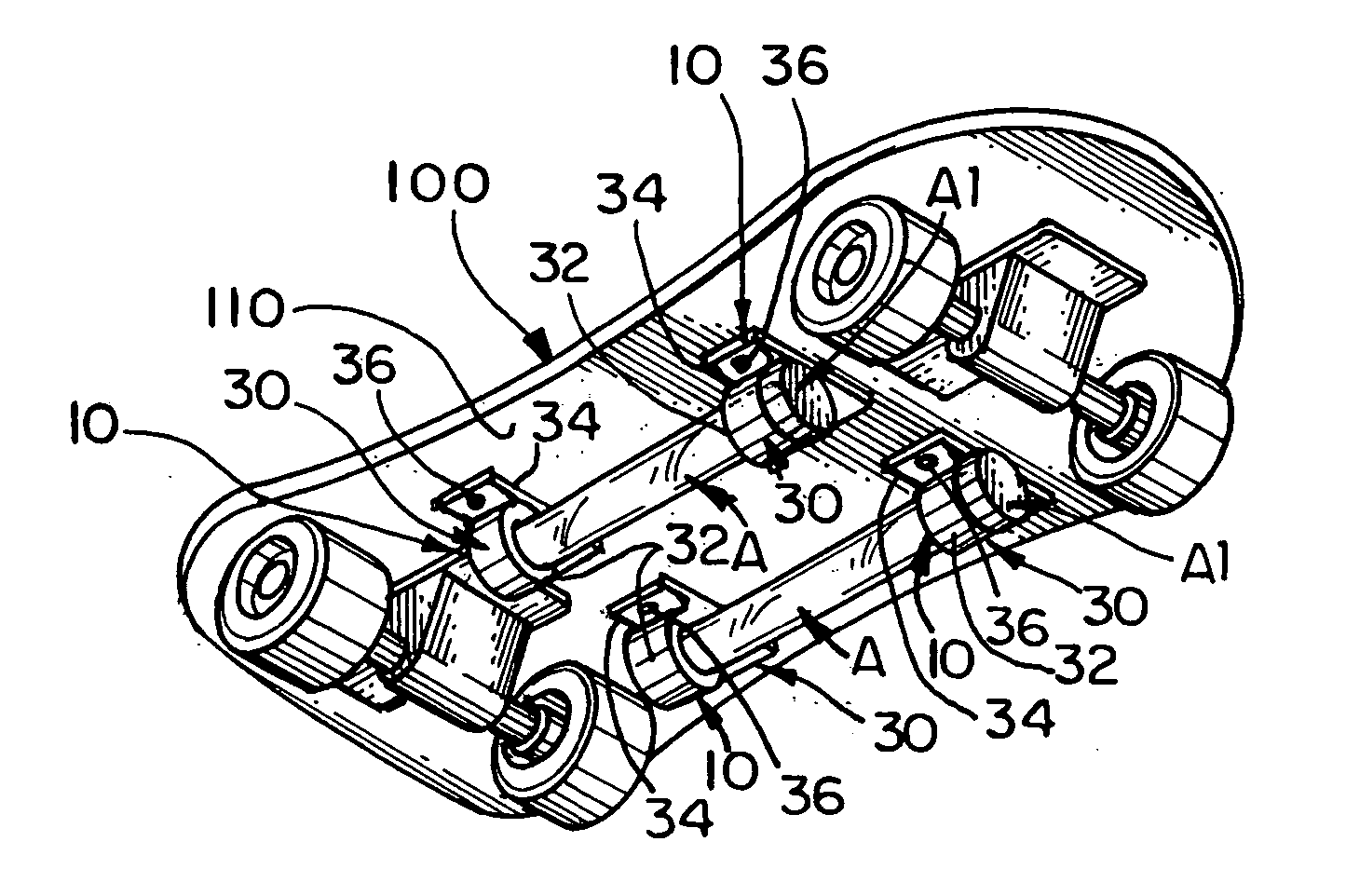
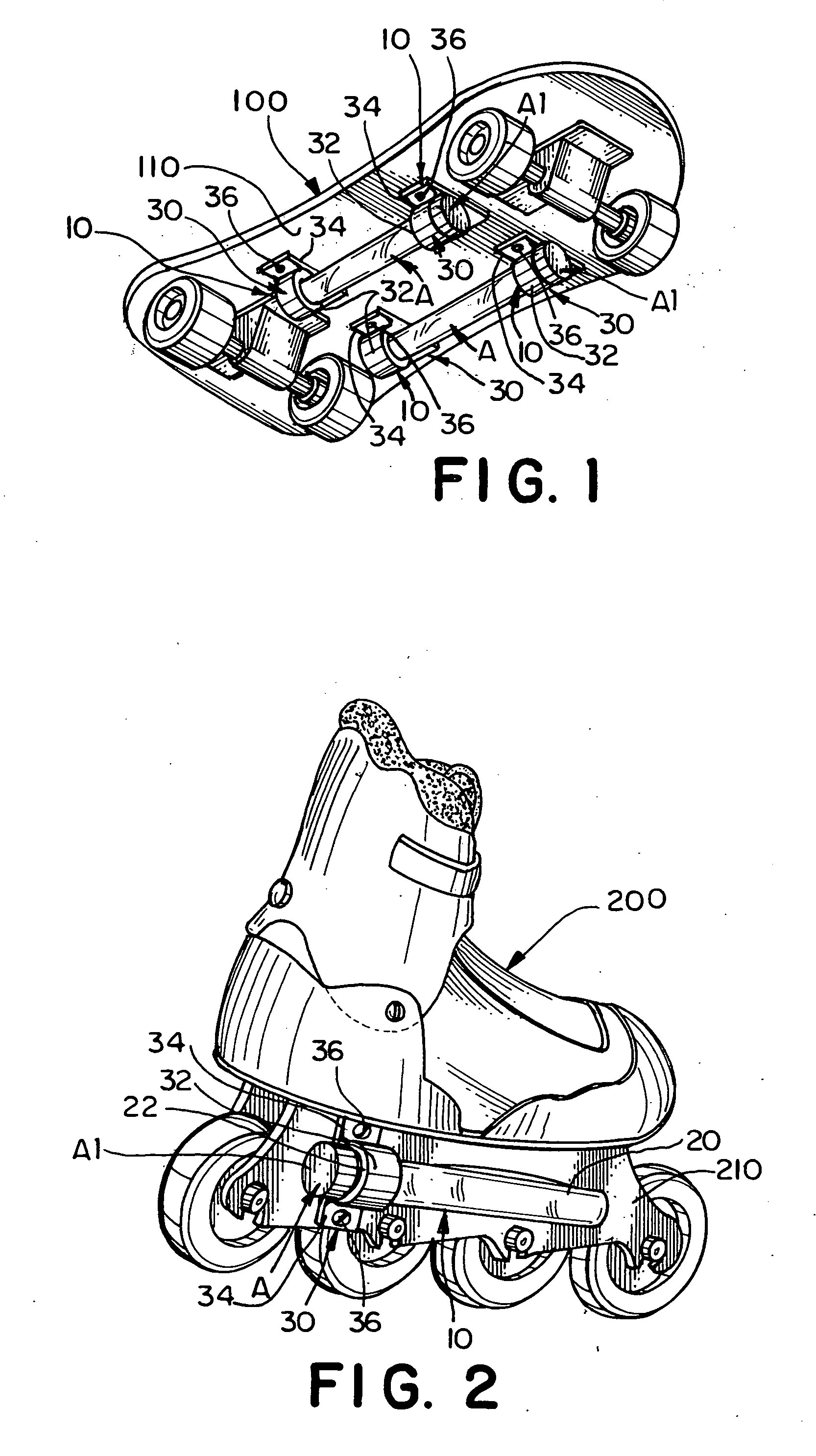
[0023] Referring to the several views of the drawings, the glow stick holding device of the present invention is shown in accordance with several embodiments thereof and is generally indicated as 10.

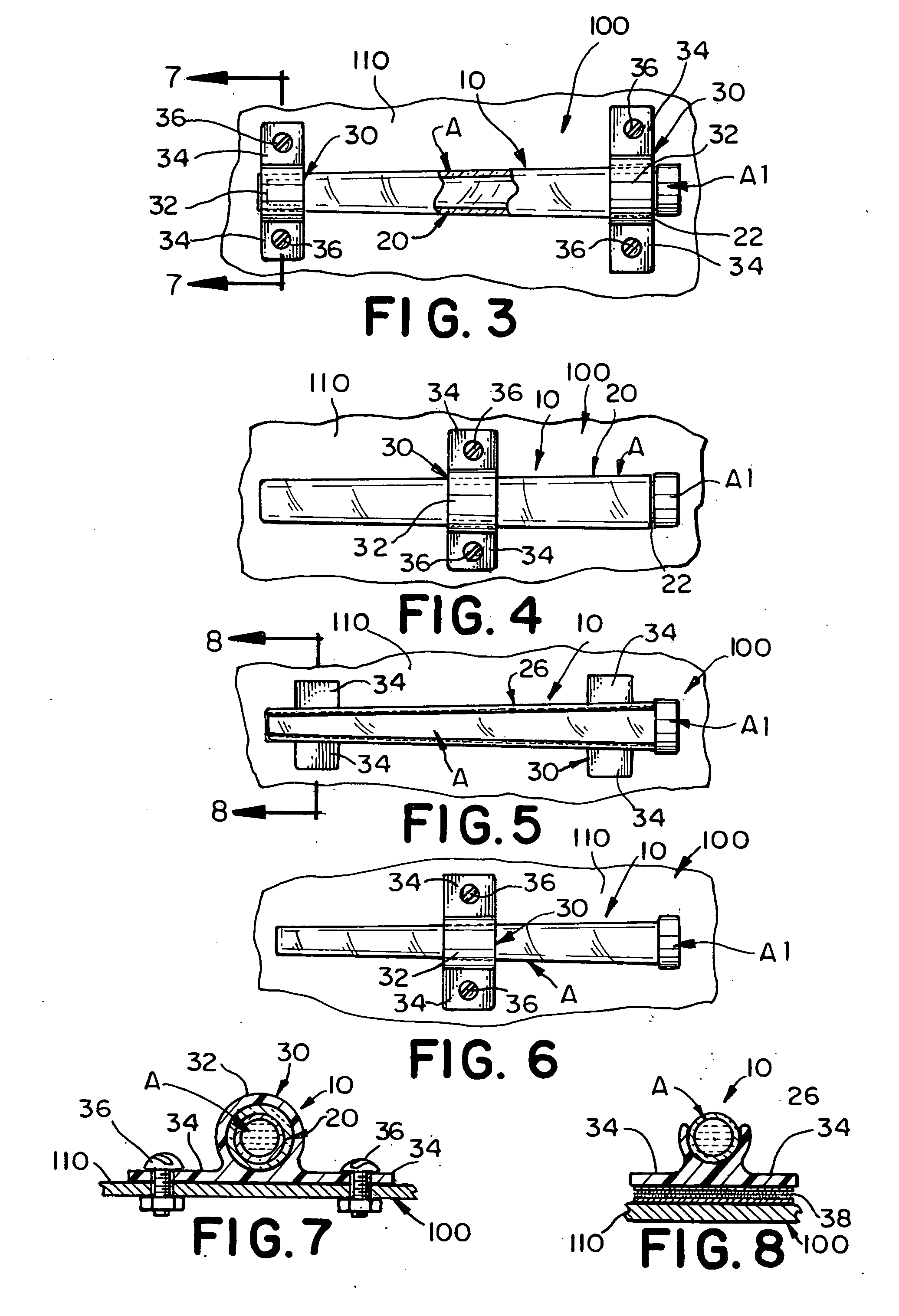
[0024] In FIG. 1, the glow stick holding device 10 is shown in use to mount conventional glow sticks A to the underside 110 of a skate board 100. The holding device 10 uses one or more brackets 30. Each bracket includes a circular collar 32 sized for snug-fitted receipt of the glow stick therein, and a mounting flange 34 having a flat surface for mating, attaching engagement with the surface of the article 100. In this particular example, the mounting flange 34 mates against the underside surface 110 of the skateboard 100 and conventional fasteners such as screws 36, hook and loop material or an adhesive is used to secure the bracket 30 to the skateboard.

[0025] In use, each glow stick A is activated by bending the outer flexible housing to break the internal glass ampule, thereby causi...


PUM


Abstract

A device for holding a chemiluminescent glow stick mounts to an article such as, but not limited to, a skateboard, an inline roller skate, a snow ski or the like. In one embodiment, the device has an open ended transparent tube for interlocking receipt of the glow stick therein. In another embodiment, a semi-cylindrical clip is sized, structured and disposed before snap fit grasping receipt of the glow stick. One or more brackets have a collar that surrounds and holds the tube or semi-cylindrical clip, and a mounting flange for attaching the bracket to the article using, for instance, screws, hook and loop fasteners, or an adhesive. Alternatively, the brackets may directly hold the glow stick. In this instance, the collar of the bracket is signed for grasping receipt of the glow stick.

Description

[0001] This application is based on provisional patent application Ser. No. 60 / 711,965 filed on Aug. 26, 2005 and I claim the benefit of the provisional patent application filing date under Title 35, United Stated Code section 119 (e).BACKGROUND OF THE INVENTION [0002] 1. Field of the Invention [0003] The present invention relates generally to mounting brackets for holding elongate cylindrical objects and, more particularly, to a device that mounts to an article and releasably holds a conventional glow stick. [0004] 2. Discussion of the Related Art [0005] Glow sticks or light sticks are well known and are often used for safety purposes (e.g. pedestrians crossing roads at night), at children's parties and when scuba diving in dark conditions. Glow sticks are commonly manufactured to include an outer elongate cylindrical housing that is formed of a flexible plastic material. The outer housing is sealed and includes a hollow interior chamber. The hollow chamber of the housing is filled...

Claims


Application Information

Patent Timeline
01 Mar 2007
Publication
US20070047216A1
IPC
F21K2/00
CPC
A63C17/01; A63C2203/14; A63C17/26; A63C17/06
Inventors
PIAZZOLLA, PAUL