Fluid transportation system
- Summary
- Abstract
- Description
- Claims
- Application Information
AI Technical Summary
Benefits of technology
Problems solved by technology
Method used
Image

Examples
first embodiment
(Schematic structure in a first embodiment, referring to FIGS. 1A and 1B)
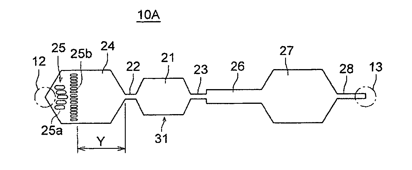
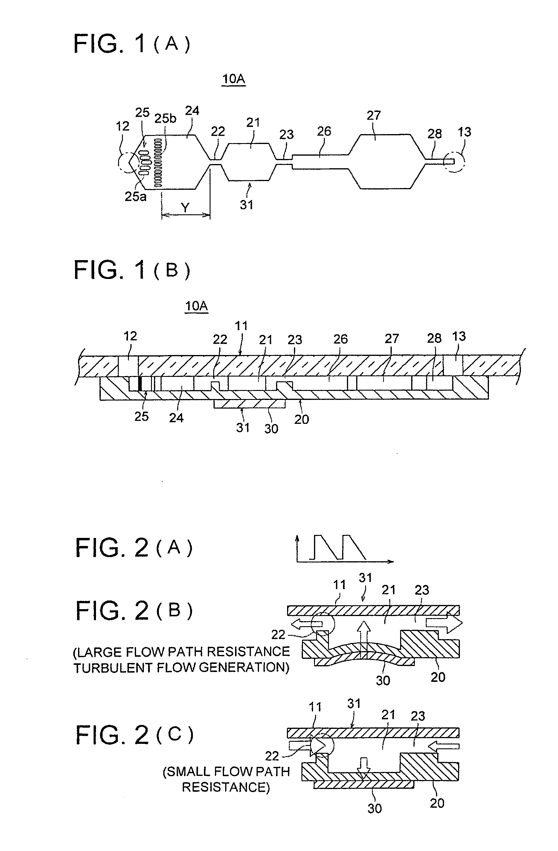
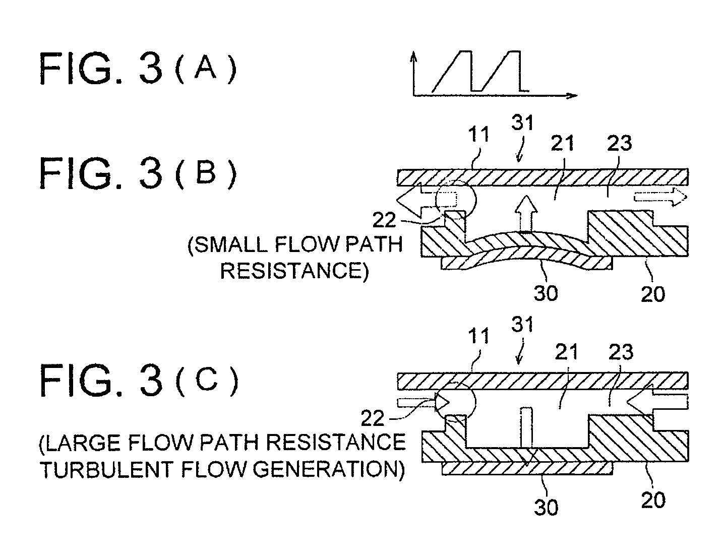
[0053] A fluid transportation system 10A in accordance with a first embodiment includes, as shown in FIG. 1B, a joint of a glass substrate 11 and thin plate 20. The glass substrate 11 is formed with an inlet 12 and outlet 13. Further, the thin plate 20 is made of a SI-based substrate that is formed by etching with a chamber 21, throttle flow paths 22 and 23, fluid reservoir 24, filtering section 25, flow path 26, pressure absorbing section 27, and narrow section 28, these communicating with each other. Further, a piezoelectric element 30 as an actuator is stuck on the outer surface of the chamber 21, and the membrane portion of the chamber 21 functions as a diaphragm.
[0054] Taking an example of concrete dimensions, the thin plate 20 is 200 μm thick; the membrane diaphragm or the like of the chamber 21 is 30 μm thick; and the throttle flow paths 22 and 23 are 25 μm deep.
[0055] The fluid reservoir 24 is formed ...
second embodiment
(Schematic Structure in a Second Embodiment, Refer to FIG. 4)
[0065] A fluid transportation system 10B in a second embodiment is constructed basically, as show in FIG. 4, by connecting, in parallel, two fluid transportation systems each including a micropump 31, described in the first embodiment, and merges transported fluids at a merging section 29a which joints flow paths 29, 29 provided on the downstream side of narrow sections 28, 28.
[0066] When plural micropumps fluid-communicate with each other through a flow path, a vibration generated by one micropump affects the operation of another micropump and tends to cause characteristic variation. However, as in the present second embodiment, when micropumps 31, 31 are connected in parallel, micropumps 31, 31 do not affect each other.
third embodiment
(Schematic Structure in a Third Embodiment, Refer to FIG. 5)
[0067] A fluid transportation system 10C in a third embodiment is constructed, as shown in FIG. 5, basically by connecting, in parallel, two fluid transportation systems each including a micropump 31, similarly to the second embodiment, and merges transported fluids at a merging section 29a which joints flow paths 29, 29 communicating with the downstream side of pressure absorbing sections 27. In the present third embodiment, instead of the narrow section 28 described in the first and second embodiment, filtering sections 25 (each including a first filtering section 25a and second filtering section 25b) are provided. Herein, the downstream side of the fluid reservoirs 24 and the upstream side of the pressure absorbing sections 27 have a circular shape in a top view.
[0068] The effects of the present third embodiment are the same as those in the first embodiment, and the effects by the parallel connection of the two micropum...
PUM
 Abstract
Description
Claims
Application Information
 - Generate Ideas
- Intellectual Property
- Life Sciences
- Materials
- Tech Scout
- Unparalleled Data Quality
- Higher Quality Content
- 60% Fewer Hallucinations
Browse by: Latest US Patents, China's latest patents, Technical Efficacy Thesaurus, Application Domain, Technology Topic, Popular Technical Reports.
© 2025 PatSnap. All rights reserved.Legal|Privacy policy|Modern Slavery Act Transparency Statement|Sitemap|About US| Contact US: help@patsnap.com