
Multi-axial spinal pedicle screw

a multi-axial, spine-to-spine technology, applied in the field of spine-to-spine pedicle screws, can solve the problems of spine not being securely fixed, spine cannot be securely fixed, and difficult to fix the spine, and achieve the effect of stably fixing the spin

Inactive Publication Date: 2007-03-01
KIM HOON +1
View PDF33 Cites 248 Cited by
  • Summary
  • Abstract
  • Description
  • Claims
  • Application Information

AI Technical Summary

Benefits of technology

[0013] Accordingly, the present invention has been made to solve the above-mentioned problems occurring in the prior art, and an object of the present invention is to provide a multi-axial spinal pedicle screw in which a head section and a tightening screw constitute a screw-coupling structure having tapered shapes in order to prevent the screws from being released even by strong external forces applied to surgical portions or by long time and continuous external forces, thereby stably fixing the spine.
[0014] It is another object of the present invention to provide a multi-axial spinal pedicle screw which is provided with at least one of a spherical chuck for surrounding and fixing the spherical articulation, a final engagement screw, and a biting plate, separately, so that a conventional structure in which the spherical articulation is supported only by point contact is converted to a structure in which the spherical articulation is fixed by surface contact and dual engagement structure, thereby maximizing the frictional engagement force between the spherical articulation and the inner surface of the head section.
[0015] It is another object of the present invention to provide a multi-axial spinal pedicle screw in which, since friction pads of a polymer are engaged with the contact portions such as the inner and outer peripheral surfaces of a spherical chuck, the inner and outer peripheral surfaces of a spherical articulation, the inner surface of a head section, and the like or prominences and depressions are formed on the contact portions, the mutual frictional engagement force between the head section and the screw rod is maximized.
[0016] It is another object of the present invention to provide a multi-axial spinal pedicle screw in which, since the thickness of a screw thread formed on the outer peripheral surface of a screw rod is maximal at the upper portion thereof, the fixing force according to the progress of rotation during the insertion of the screw rod into the pedicle is maximized.

Problems solved by technology

Further, the multi-axial spinal pedicle screw does not have the engagement force and resistance required for fixing a damaged spine that it has a difficulty in fixing the spine.
But, since the above-mentioned structure cannot prevent the operation of the external forces, the screw member may be released over time or by the movements of the body and thus the spine cannot be securely fixed.
Further, in the case of the multi-axial spinal pedicle screw, since the fixing force is secured by inserting the spherical articulation of the upper portion of the screw rod into the head section and then using the contact friction with the inner surface of the head section, in order to engage the screw rod with the head section, it is difficult to fix the spine if a slide is generated between the spherical articulation and the inner surface of the head section, even in the case in which the screw is relatively stably engaged.
Especially, in fixing the spherical articulation in a conventional manner, since the contact with the inner surface of the head section is almost a point contact, it is difficult to secure frictional fixing forces.

Method used


Image

  • Multi-axial spinal pedicle screw
  • Multi-axial spinal pedicle screw
  • Multi-axial spinal pedicle screw

Examples


Embodiment Construction

[0081] Hereinafter, preferred embodiments of the present invention will be described with reference to the accompanying drawings.

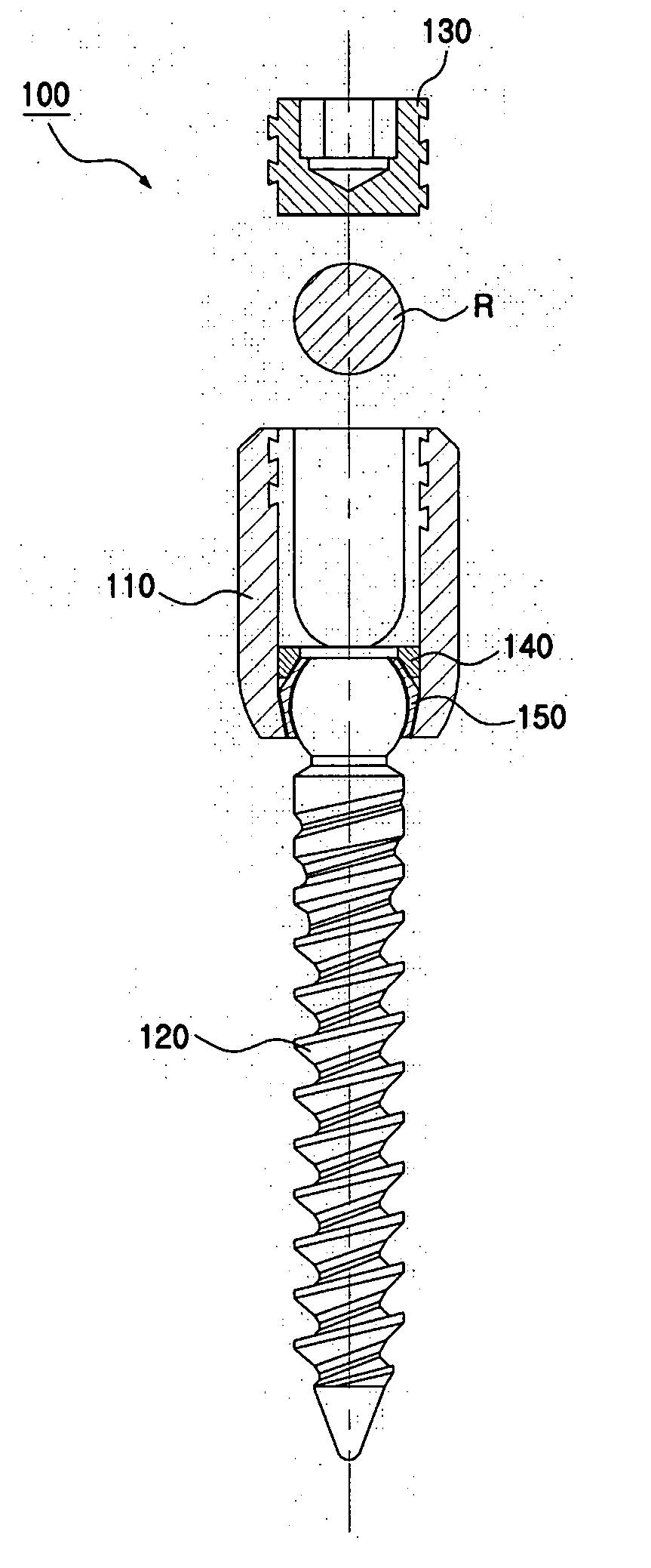
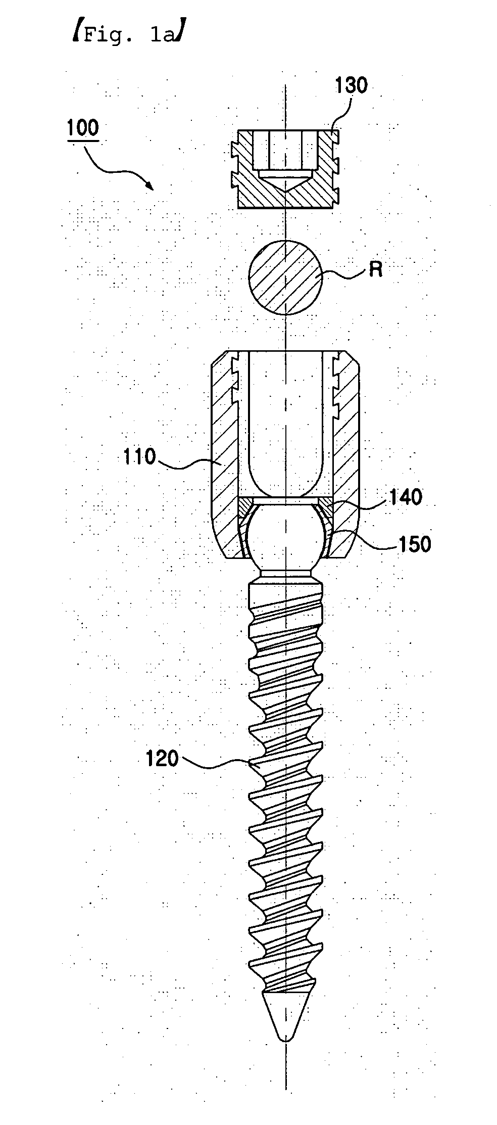
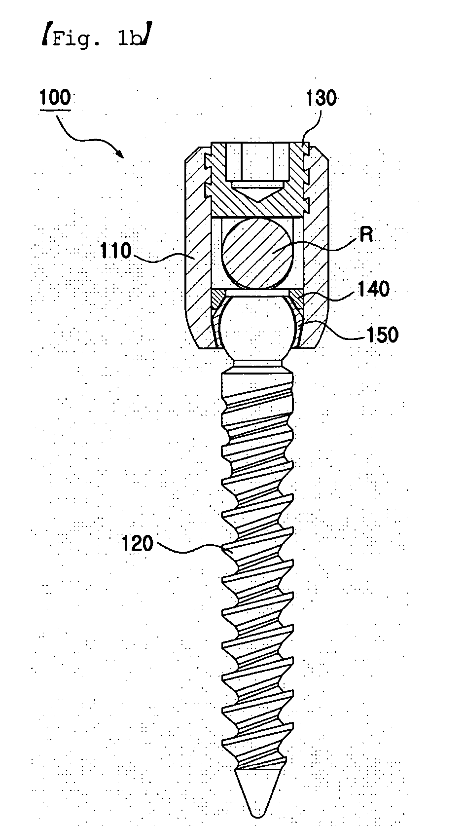
[0082]FIGS. 1a and 1b are cross-sectional views for showing the engagement structure of a multi-axial spinal pedicle screw according to a preferred embodiment of the present invention. FIG. 1a shows a state before the engagement of the spinal rod, and FIG. 1b shows a state after the engagement of the spinal rod. FIG. 2 is an exploded view for showing the multi-axial spinal pedicle screw shown in FIG. 1.

[0083] Referring to FIGS. 1 and 2, the multi-axial spinal pedicle screw 100 according to a preferred embodiment of the present invention includes a screw rod 120 in which a spherical articulation 121 is integrally formed at an upper portion thereof, a spherical chuck 150 having a plurality of claws 151 and 152 for surrounding and fixing the spherical articulation 121, a head section 110 in which a receiving hole 113 for receiving the spherical chuck 150, w...


PUM


Abstract

Disclosed is a multi-axial spinal pedicle screw engaged with a spinal rod and inserted into and fixed to a pedicle. The multi-axial spinal pedicle screw includes: a screw rod in which a spherical articulation is integrally formed at an upper portion thereof, the screw rod being inserted into and fixed to the pedicle through a screw thread formed on the outer surface of a lower portion thereof; a spherical chuck having a plurality of claws, for surrounding and fixing the spherical articulation; a head section in which a receiving hole for receiving the spherical chuck fixing the spherical articulation is formed at a lower portion thereof so as to penetrate the lower portion, a rod receiving channel for receiving the spinal rod is opened upward, and an engagement screw root is formed on the inner surface of the rod receiving channel; and a tightening screw in which an engagement screw thread corresponding to the engagement screw root is formed on the outer surface thereof, the tightening screw being engaged with the head section through the rod receiving channel to fix the spinal rod.

Description

BACKGROUND OF THE INVENTION [0001] 1. Field of the Invention [0002] The present invention relates to a spinal pedicle screw, and more particularly to a multi-axial spinal pedicle screw which can rotate a head section according to conditions during a surgery and includes a strong fixing force to prevent the release thereof after surgery. [0003] 2. Description of the Prior Art [0004] A spine is a very complex system of a connection structure of bones which provide a body with a support portion and protect delicate spinal cords and nerve roots. A spine includes a series of stacked spinal columns and a pedicle of each spinal column includes the interior portion formed of relatively weak cavernous bones and the exterior portion formed of relatively strong cortical bones. [0005] The treatment of a disorder related to a spine generally includes an indirect method in which physical treatments are performed and a direct method in which a separate fixation apparatus is mounted to a pedicle to...

Claims


Application Information

Patent Timeline
IPC IPC(8): A61F2/30
CPCA61B17/7037A61B17/7032A61B17/70
Inventor AHN, SAE YOUNGLIM, JAE KWANCHOI, JONG MYEONKIM, SEO KONKIM, HOON
Owner KIM HOON
Learn More