Preloaded injector for intraocular lenses and methods of making and using

a technology of intraocular lens and injector, which is applied in the field of ophthalmic surgical devices and methods, can solve the problems of trauma to the surrounding tissues of the eye, high care to be taken in the handling of intraocular lens, and high surgical risk

Inactive Publication Date: 2007-03-01
BAUSCH & LOMB INC
View PDF1 Cites 111 Cited by
  • Summary
  • Abstract
  • Description
  • Claims
  • Application Information

AI Technical Summary

Benefits of technology

[0014] The relative positioning of the IOL shuttle, the IOL and the injector device is such that upon attaching the proximal and distal sections of the injector device together, the IOL becomes preferentially positioned inside the injector device. The IOL thus becomes positioned in a particular orientation inside the injector device relative to the plunger tip. This IOL loaded position results in the leading haptic being correctly aligned in the shuttle, and the trailing haptic and optic aligning with the plunger tip so that upon advancement of the plunger, the plunger tip will engage the IOL optic in the intended manner without obstruction or jamming of the trailing haptic.

Problems solved by technology

Since IOLs are very small and delicate articles of manufacture, great care must be taken in their handling.
Should the IOL be damaged during delivery into the eye, the surgeon will most likely need to extract the damaged IOL from the eye and replace it with a new IOL, a highly undesirable surgical outcome.
Should the IOL be expelled from the tip too quickly or in the wrong orientation, the surgeon must further manipulate the IOL in the eye which could result in trauma to the surrounding tissues of the eye.
Due to the delicate nature of the IOL, there is a risk that the nurse and / or surgeon will inadvertently damage the IOL and / or incorrectly load the IOL into the injector device resulting in a failed implantation.
Direct handling and / or loading of the IOL into the injector by the nurse and / or surgeon is therefore undesirable.

Method used


Image

  • Preloaded injector for intraocular lenses and methods of making and using
  • Preloaded injector for intraocular lenses and methods of making and using
  • Preloaded injector for intraocular lenses and methods of making and using

Examples


examples

Testing of Injector Devices with Surfactants

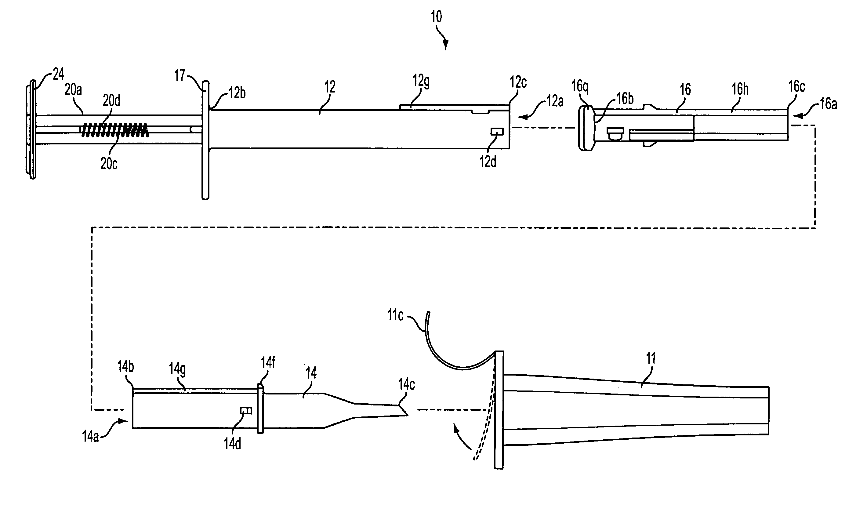
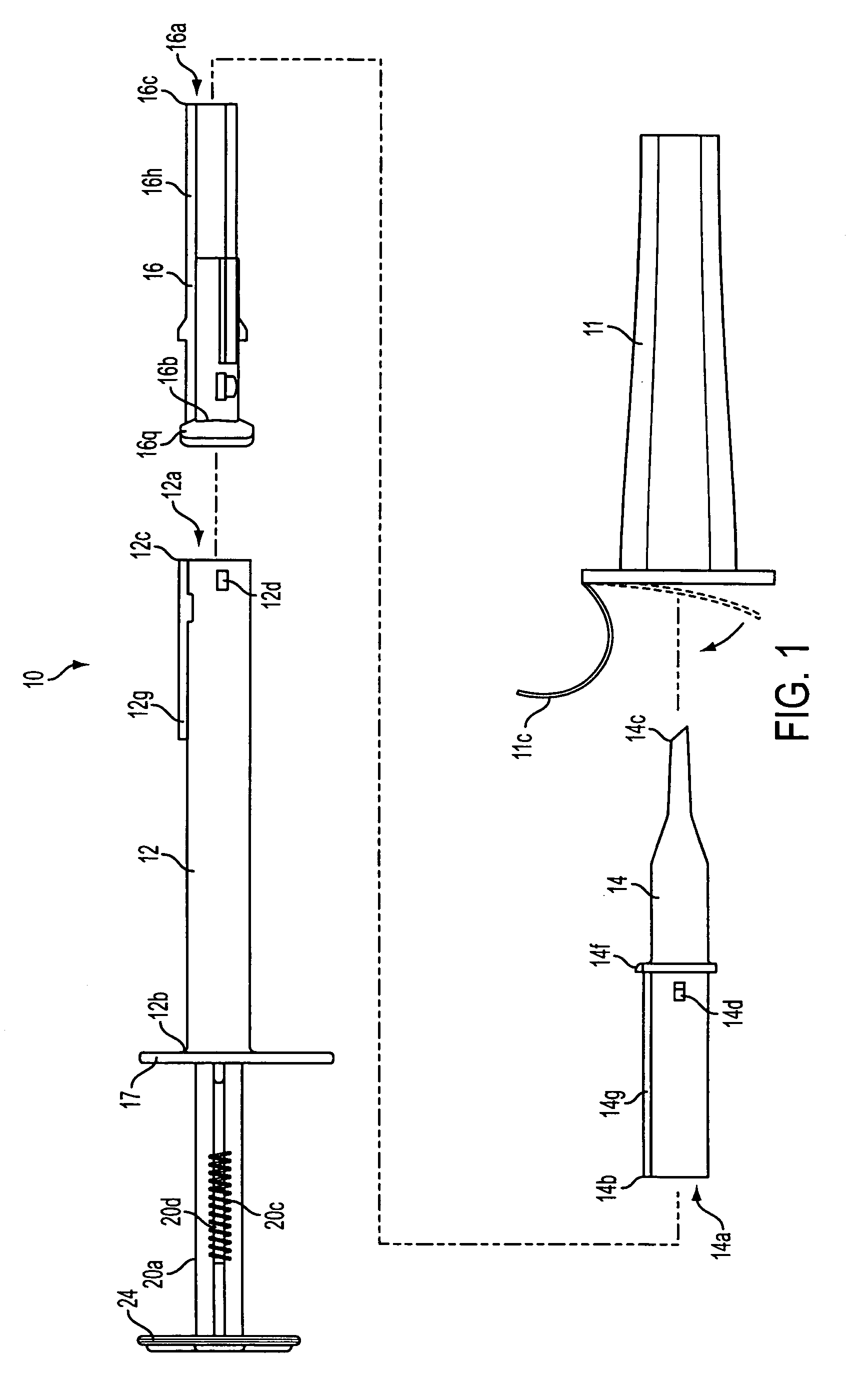
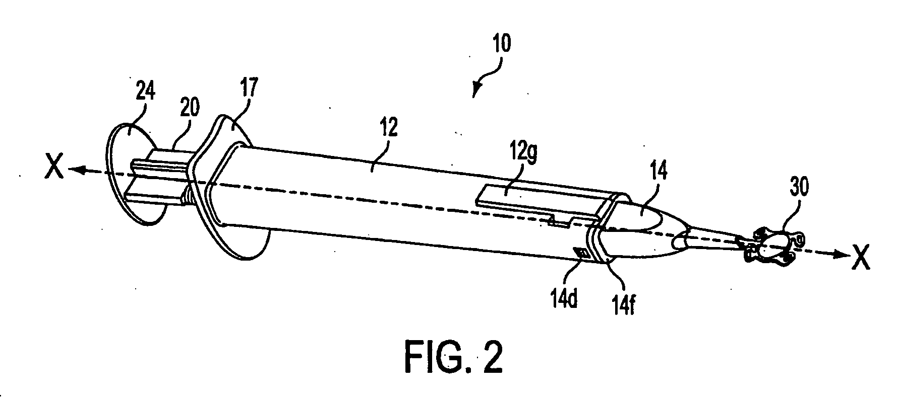
[0059] In this testing, Bausch and Lomb Incorporated's Akreos Adapt™ lenses were used with injectors of the type shown in FIGS. 1 and 2. The injector components were made of PFA. The procedure was as follows. A lens 30 (having various optical power in the range from +10.0 d to +23.5 d) was immersed in a surfactant solution for a few seconds and then loaded in shuttle 16, which was then positioned in distal section 14. Distal section 14 with shuttle 16 and lens 30 positioned therein was placed in the surfactant solution for a few minutes. A proximal section 12 having a plunger 20 inserted therein was attached to distal section 14, and ejection of lens 30 was tested. The ease of ejection, as judged qualitatively by a required amount of force, was noted. All reported surfactant concentrations are in percent by weight.

[0060] Ejection was easy with a +11.0 d-power lens using 1% Polysorbate 80 solution; a +10 d-power lens and a +21.0 d-power l...


PUM


Abstract

Apparatus and method for preloading an intraocular lens (30, 30′) in a component of an injector device (10) and for reducing the force used to eject the intraocular lens (30, 30′) therefrom are disclosed. The intraocular lens (30, 30′) is positioned in a shuttle (16, 16′) which is positioned inside a distal section (14, 14′) of the device (10). The shuttle (16, 16′), IOL (30, 30′), and distal section (14, 14′) are positioned and sealed in a vial (11) of solution that comprises a surfactant. At the time of use, a user opens the vial (11) and attaches a proximal section (12) having a plunger (20) to the distal section (14, 14′) located in the vial (11). The proximal section (12) is then lifted away from the vial (11) together with the distal section (14, 14′), and the shuttle (16, 16′) and IOL (30, 30′) located in the distal section (14, 14′). The plunger (20) is advanced to express the IOL (30, 30′) from the distal tip (14c, 14c′) of the distal section (14, 14′).

Description

BACKGROUND OF THE INVENTION [0001] The present invention relates to ophthalmic surgical devices and methods. More particularly, the present invention relates to a device and method for inserting an intraocular lens (IOL) into an eye, wherein the IOL may be conveniently preloaded in and packaged together with the injector device. [0002] IOLs are artificial lenses used to replace the natural crystalline lens of the eye when the natural lens has cataracts or is otherwise diseased. IOLs are also sometimes implanted into an eye to correct refractive errors of the eye in which case the natural lens may remain in the eye together with the implanted IOL. The IOL may be placed in either the posterior chamber or anterior chamber of the eye. IOLs come in a variety of configurations and materials. Some common IOL styles include the so-called open-looped haptics which include the three-piece type having an optic and two haptics attached to and extending from the optic; the one-piece type wherein...

Claims


Application Information

Patent Timeline
Patent Type & Authority Applications(United States)
IPC IPC(8): A61F2/16
CPCA61F2/1691A61F2/1678
Inventor BESSIERE, BENOITPREVITALI, SANDRACESSES, CHRISTOPHE
Owner BAUSCH & LOMB INC
Why Eureka
Try Eureka