Field display system

a display system and field technology, applied in the field of display systems, can solve the problems of physical ultimate size limitation of electronic signs

Inactive Publication Date: 2007-03-08
MITSUBISHI ELECTRIC RES LAB INC
View PDF6 Cites 26 Cited by
  • Summary
  • Abstract
  • Description
  • Claims
  • Application Information

AI Technical Summary

Problems solved by technology

A major limitation for electronic signs has been their physical size.
Even though the signs have gotten much larger over the years, their ultimate size is limited by the amount of available space.

Method used


Image

  • Field display system
  • Field display system
  • Field display system

Examples


Embodiment Construction

System Structure

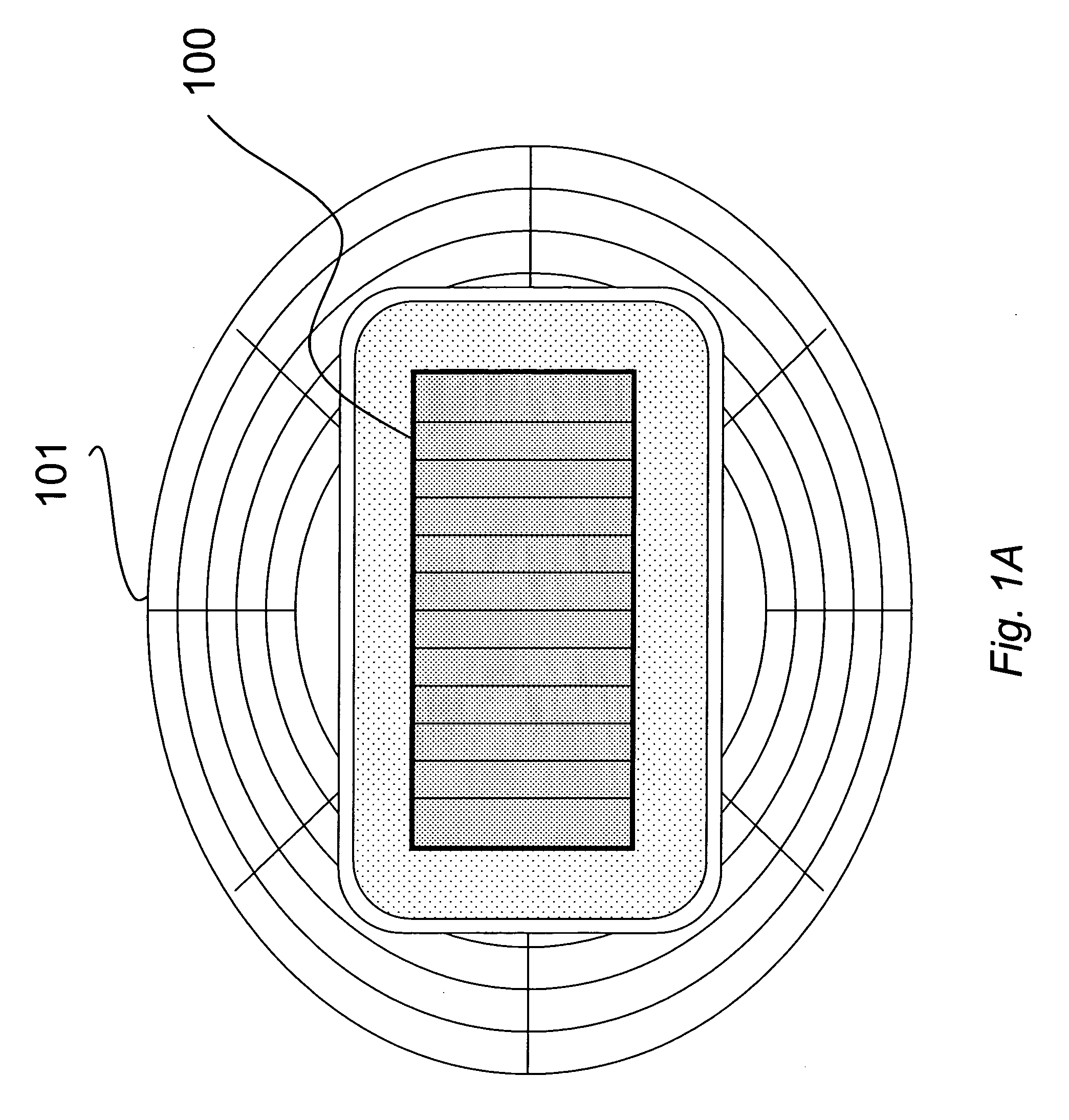
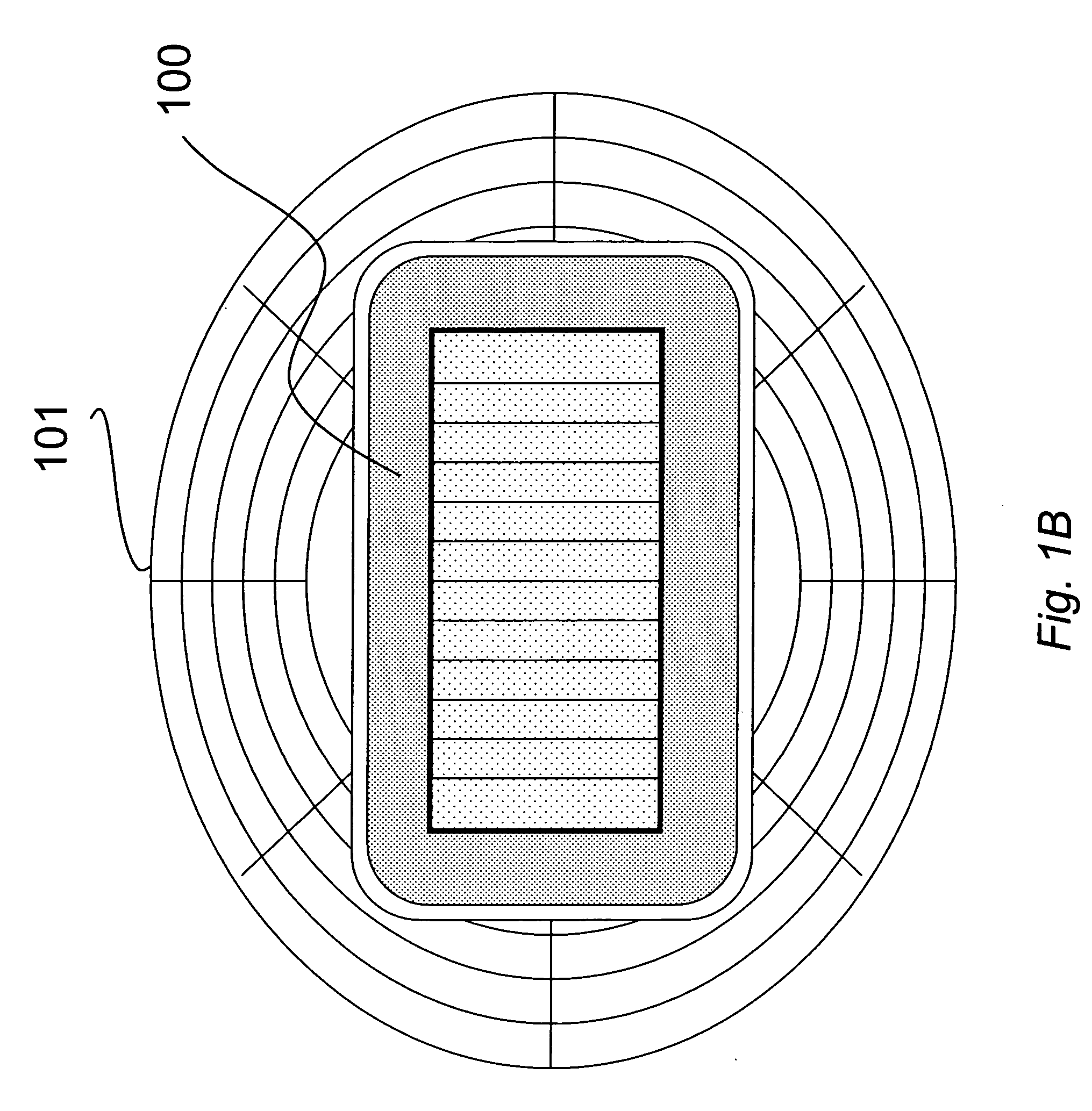
[0013]FIG. 1A shows an arrangement of a display system 100 according to one embodiment of the invention with respect to the stadium 101. The display system 100 is integrated with and extends over the playing surface 101. It should be noted that the display area can be limited to a portion of the playing surface. In contrast, FIG. 1B shows the display system 100 only in the ‘out-of-bounds’ area around the playing surface.

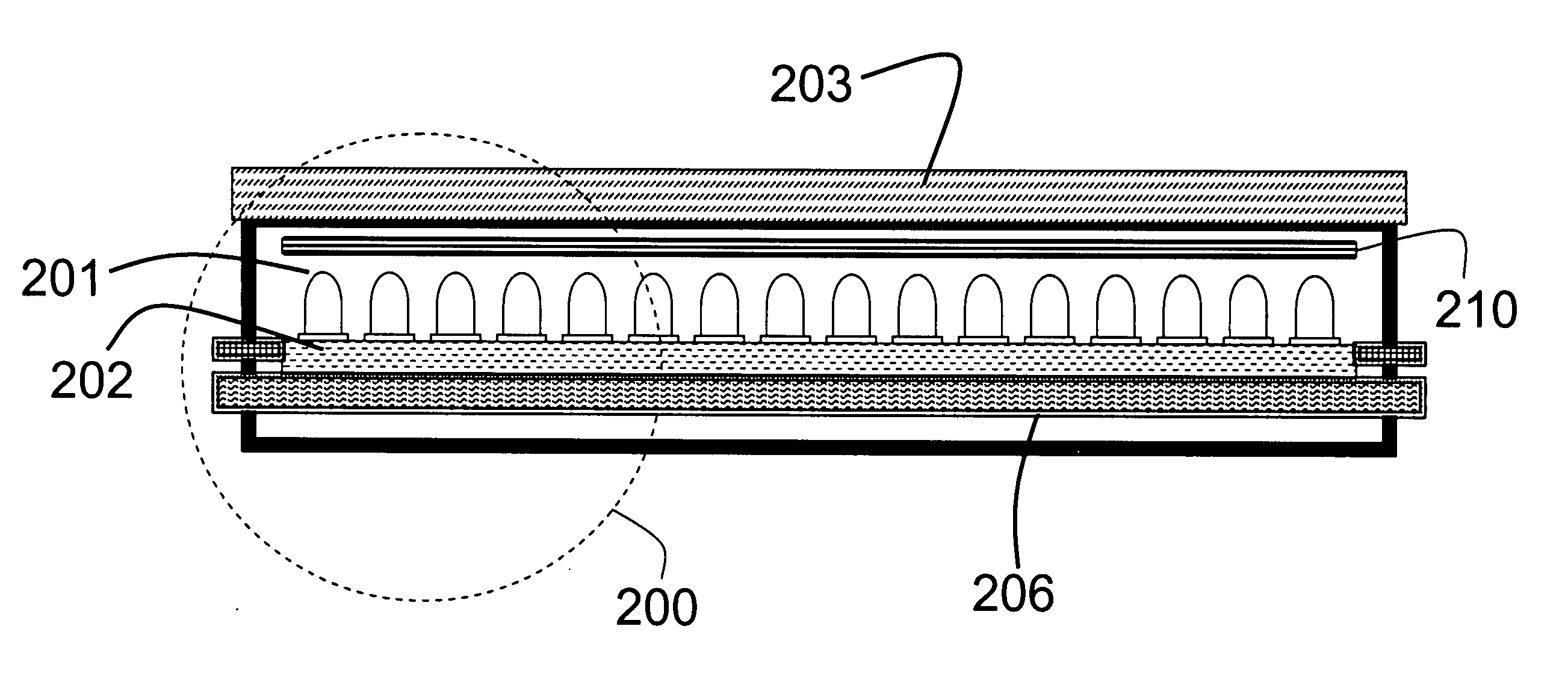
[0014]FIG. 2 shows a cut away side view of a portion of the display system. The display includes display elements 200 embedded in the playing surface. Each element includes an array of light emitters 201 arranged on a substrate, e.g., a circuit board 202. The circuit board provides mechanical and electrical connections for the light emitters. The light emitters can emit colored light, e.g., red, green, and blue (RGB) to provide a full range of colors. The light emitters can be incandescent light or solid state light emitters such as LEDs. Alternativ...


PUM


Abstract

A display system includes display elements embedded in a playing surface. The display elements are configured to display images or video in the playing surface. The playing surface can be a soccer field, a football field, a rugby field, a baseball field, a track field, a horse racing track, a tennis court, a basketball court, a performance stage, and combinations thereof.

Description

FIELD OF THE INVENTION [0001] This invention relates generally to display systems, and more particularly to display systems for sporting events. BACKGROUND OF THE INVENTION [0002] Stadiums, arenas and other venues for sporting events have long featured scoreboards and other displays. These displays help spectators to keep track of the sporting event, as well as other related events. In the early days, number placards were put up by hand on sign boards. Over time, these systems have become more automated, first with mechanical systems and later with electronic systems. But, even in the early days, it was realized that because so many spectators are looking at the scoreboard, it is an excellent place for advertising and thus a source for revenue. [0003] Over time, electronic scoreboards have evolved to include the ability to show images and videos. This enables more sophisticated advertising, and enhances the event experience for the spectator by showing player close-ups, instant repl...

Claims


Application Information

Patent Timeline
Patent Type & Authority Applications(United States)
IPC IPC(8): F21V5/00
CPCG09F19/228G09F19/22
Inventor DIETZ, PAUL H.YERAZUNIS, WILLIAM S.RASKAR, RAMESH
Owner MITSUBISHI ELECTRIC RES LAB INC
Why Eureka
Try Eureka