
A horse racing spindle seat for a knitting machine

A technology of knitting machines and spindle bases, which is applied in the field of knitting machines, can solve the problems of reducing production efficiency and product quality, time-consuming and laborious maintenance, and reducing production efficiency, so as to improve production efficiency and product quality, reduce the probability of damage, and improve production efficiency. efficiency effect

Active Publication Date: 2022-05-13
衡阳新新纺织机械有限公司
View PDF5 Cites 0 Cited by
  • Summary
  • Abstract
  • Description
  • Claims
  • Application Information

AI Technical Summary

Problems solved by technology

[0002] As we all know, the knitting machine is a special machine for weaving factories to manufacture knitted products. It uses the method of intersecting warp and weft to weave the thread into various knitted products. In the control of warp and weft intersection, the warp lifting ring drives the warp upward, It moves downward to form a weft threading opening for the circular motion of the horse spindle to pass through the upper and lower warp threads to form intersecting warp and weft woven products. Today, the horse spindle of the knitting machine runs at high speed and generates a large friction force between the spindle seat , so that the pulleys of the racing spindles generate a lot of heat and cannot be discharged in time, which leads to the machine stopping due to the damage of the pulleys, and the maintenance takes time and effort, thus greatly reducing the production efficiency. In winter, the temperature is relatively cold, and the line is affected by the temperature The wire becomes brittle and easy to break, which greatly reduces the production efficiency and product quality

Method used

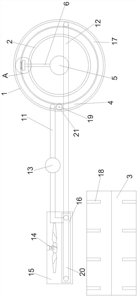

Image

  • A horse racing spindle seat for a knitting machine
  • A horse racing spindle seat for a knitting machine
  • A horse racing spindle seat for a knitting machine

Examples


Embodiment Construction

[0020] The following will clearly and completely describe the technical solutions in the embodiments of the present invention with reference to the accompanying drawings in the embodiments of the present invention. Obviously, the described embodiments are only some, not all, embodiments of the present invention. Based on the embodiments of the present invention, all other embodiments obtained by persons of ordinary skill in the art without making creative efforts belong to the protection scope of the present invention.

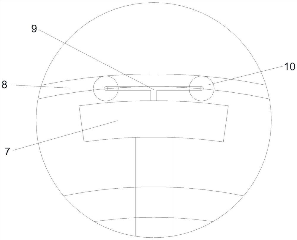
[0021] see Figure 1-4 , a kind of braiding machine racing spindle seat of the present invention comprises a body 1, a wire rack 3 and a heat sink 15, the middle part of the rear end of the body 1 is provided with a fixing seat 2, which plays the role of supporting the body 1, and the inside of the outer wall of the body 1 A cooling cavity 4 is provided in the middle of the cooling cavity 4, and a cooling tube 17 and oil-filled heat transfer oil are installed ...


PUM


Abstract

The present invention relates to the technical field of braiding machines, and specifically relates to a horse racing spindle seat of a braiding machine, which can reduce the heat between the horse racing spindle and the spindle seat and provide heat for the wire, including a machine body, a wire frame and a radiator, and the body of the machine The middle part of the rear end is provided with a fixed seat, the inner middle part of the outer wall of the body is provided with a cooling cavity, the middle part of the body is provided with a rotating shaft, the middle part of the top of the rotating shaft is provided with a transmission shaft, the top of the transmission shaft is provided with a horse racing spindle, and the top of the horse racing spindle is provided with a There is a bracket, the four corners of the bracket are respectively equipped with pulleys, the middle part of the inner wall of the machine body is equipped with a spindle base, the inside of the cooling chamber is equipped with a condensation pipe, the rear end of the left part of the condensation pipe is provided with an air outlet pipe, and the rear end of the right part of the condensation pipe is installed There is an air outlet pipe, a compressor is arranged in the middle of the air outlet pipe, a fan is arranged at the top of the radiator, a heat sink is arranged at the bottom of the radiator, a heat dissipation pipe is arranged inside the heat radiator, and an inlet is arranged at the other end of the heat radiator. trachea.

Description

technical field [0001] The invention relates to the technical field of knitting machines, in particular to a horse racing spindle seat of a knitting machine. Background technique [0002] As we all know, the knitting machine is a special machine for weaving factories to manufacture knitted products. It uses the method of intersecting warp and weft to weave the thread into various knitted products. In the control of warp and weft intersection, the warp lifting ring drives the warp upward, It moves downward to form a weft threading opening for the circular motion of the horse spindle to pass through the upper and lower warp threads to form intersecting warp and weft woven products. Today, the horse spindle of the knitting machine runs at high speed and generates a large friction force between the spindle seat , so that the pulleys of the racing spindles generate a lot of heat and cannot be discharged in time, which leads to the machine stopping due to the damage of the pulleys...

Claims


Application Information

Patent Timeline
Patent Type & Authority Patents(China)
IPC IPC(8): D04C3/48
CPCD04C3/48
Inventor 曾贤通彭来深焦贤伟谭新球
Owner 衡阳新新纺织机械有限公司
Learn More