
Stirring machine

A technology for mixers and power mechanisms, which is applied to mixers with rotating agitation devices, mixers, dissolvers, etc., can solve the problems of increased energy consumption of motors and easy damage to equipment, and achieve reduced damage probability, reduced power consumption, and cost saving effect

Active Publication Date: 2015-03-25
GOLD EAST PAPER JIANGSU
View PDF5 Cites 17 Cited by
  • Summary
  • Abstract
  • Description
  • Claims
  • Application Information

AI Technical Summary

Problems solved by technology

[0005] The technical problem mainly solved by the present invention is to provide a mixer, which can solve the technical problem that the motor of the mixer must bear the radial force in the prior art, so that the energy consumption of the motor increases and the equipment is easily damaged

Method used


Image

  • Stirring machine

Examples


Embodiment Construction

[0018] The present invention will be described in detail below in conjunction with the accompanying drawings and embodiments.

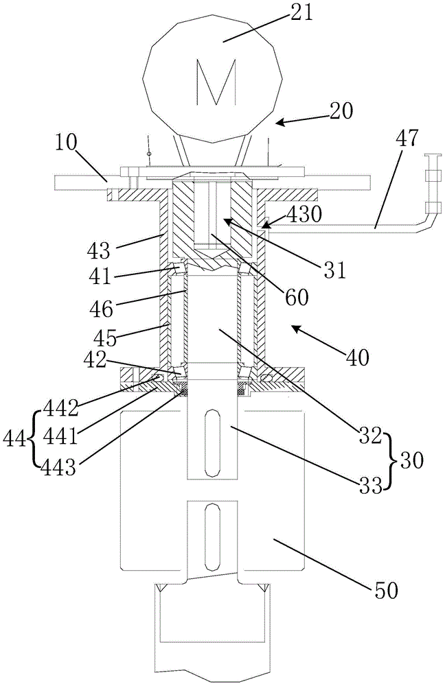
[0019] see figure 1 , figure 1 It is a structural schematic diagram of a preferred embodiment of the mixer of the present invention. In this embodiment, the mixer includes: a base plate 10 , a power mechanism 20 , a rotating shaft 30 , a suspension device 40 and a mixing blade 50 .

[0020] The power mechanism 20 is fixed on the base plate 10 . The rotating shaft 30 is connected to the power mechanism 20 and driven to rotate by the power mechanism 20 . The suspension device 40 is fixed on the base plate 10 and used for supporting the rotating shaft 30 to rotate. The stirring blade 50 is fixed on the rotating shaft 30 . The stirring blade 50 is inserted into the material to be stirred, and the stirring blade 50 rotates with the rotating shaft 30 . Preferably, the power mechanism 20 is disposed above the base plate 10 , and the suspension device 4...


PUM


Abstract

The invention discloses a stirring machine. The stirring machine comprises a base plate, a power mechanism, a rotating shaft, a suspension device and a stirring blade, wherein the power mechanism is fixed on the base plate, the rotating shaft is connected with the power mechanism and is driven to rotate by the power mechanism, the suspension device is fixed on the base plate and is used for supporting the rotating shaft for rotating, and the stirring blade is fixed on the rotating shaft. Due to the above mode, the power consumption of the power mechanism can be reduced, the damage probability of the power mechanism can be reduced and the cost can be saved.

Description

technical field [0001] The invention relates to the field of mechanical equipment, in particular to a mixer. Background technique [0002] The required paint is sprayed on the paper web during the papermaking process of the paper machine. Due to paper breaking and cleaning, some waste paint will flow into the waste water pool together with the cleaning water of the table. Because the specific gravity of the paint is greater than that of water, the wastewater tank needs to be stirred with a mixer to avoid paint precipitation and facilitate wastewater purification. [0003] Due to the high viscosity of the paint, if it is not stirred in time, the paint will settle at the bottom of the waste water tank. The traditional solution is generally to add a mixer for mixing, but due to the self-weight of the mixing blade and the intermediate shaft, the mixer motor must bear the radial force, which increases the energy consumption of the motor and the equipment is easily damaged. [0...

Claims


Application Information

Patent Timeline
Patent Type & Authority Applications(China)
IPC IPC(8): B01F7/16
Inventor 崔海戴林
Owner GOLD EAST PAPER JIANGSU
Learn More