Disposable sanitary mixing apparatus and method

a sanitary and mixing equipment technology, applied in the direction of mixers, mixer accessories, mixing, etc., can solve the problems of difficult to know if the operator has satisfactorily performed the cleaning, the seal is dismantled, and the cleaning process is time-consuming and laborious, so as to achieve a high-quality, sterile internal environment, the effect of convenient and practical us

Active Publication Date: 2007-03-08
SPX FLOW INC
View PDF16 Cites 48 Cited by
  • Summary
  • Abstract
  • Description
  • Claims
  • Application Information

AI Technical Summary

Benefits of technology

[0006] Some embodiments of the invention provide a mixing apparatus and method that can provide a high...

Problems solved by technology

In order to clean this type of device thoroughly enough for some applications, it is necessary to dismantle the seal and undergo a time consuming and l...

Method used


Image

  • Disposable sanitary mixing apparatus and method
  • Disposable sanitary mixing apparatus and method
  • Disposable sanitary mixing apparatus and method

Examples


Embodiment Construction

[0018] Some embodiments of the invention provide a mixing apparatus and method that can provide a highly clean or sterile internal environment at a mixing site, while also being convenient and practical to use. Preferred embodiments of the invention will now be described with reference to the drawing figures in which like reference numerals refer to like parts throughout.

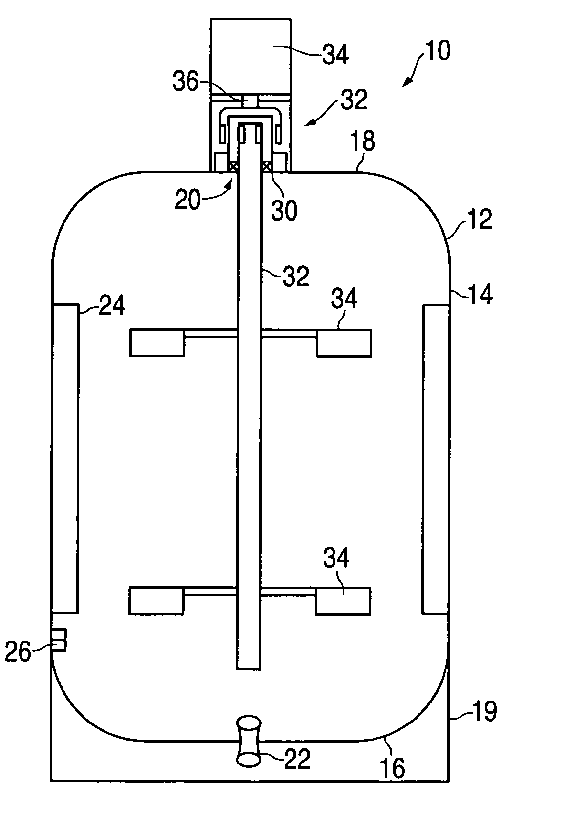
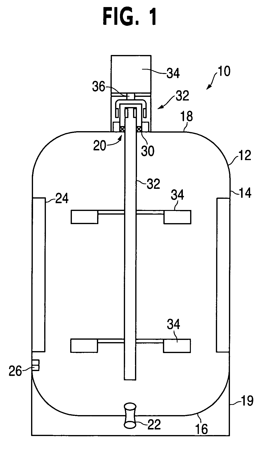
[0019]FIG. 1 illustrates a mixing apparatus 10, which includes a vessel 12, which is generally cylindrical with two closed ends. The vessel 12 thus has a cylindrical side wall 14 a lower end 16 and an upper end 18. The vessel 12 also has a dome 20 associated therewith as will be described in more detail below. The vessel 14 may also include a molded in base or set of feet 19. The vessel 12, including its sidewall 14 and ends 16 and 18, can be made of any suitable material, but in some instances it is preferable that it be molded from a plastic material.

[0020] As is described in more detail below, one benefit of so...


PUM


Abstract

A mixing apparatus and method uses a disposable assembly including a closed vessel with a rotating shaft supported in the vessel. The shaft has radially extending impellers. The shaft is driven via an external magnetic drive system. The vessel can be cleaned during manufacture and discarded after use.

Description

FIELD OF THE INVENTION [0001] The invention pertains generally to mixing devices, and more particularly pertains to mixing devices having a closed mixing vessel and rotating shaft impellers. BACKGROUND OF THE INVENTION [0002] Rotating impeller type mixing devices are in wide use in industry. For example, there are many types of mixing devices that generally utilize a mixing vessel to hold the fluid and / or other mixing material, which is to be mixed or agitated. The vessels can be of any suitable shape, including for example cylindrical, oval, square, etc. A motor driven impeller shaft extends into the vessel and has paddle type impellers radially extending therefrom so that when the shaft is rotated the impellers agitate and / or mix the material inside the vessel. [0003] In some applications, such as particularly sanitary applications including, for example, pharmaceutical or food operations, it is generally desirable for the mixing device to be cleaned into a highly sterile conditio...

Claims


Application Information

Patent Timeline
IPC IPC(8): B01F13/08B01F27/91B01F27/93
CPCB01F7/186B01F13/0827B01F2215/0032B01F15/00915B01F15/00071B01F27/9021B01F33/4534B01F35/146B01F35/55B01F2101/22B01F33/453
Inventor KOCIENSKI, ANTHONY C.
Owner SPX FLOW INC
Why Eureka
Try Eureka