Circularly polarizing plate, vertically alignment type of liquid crystal display panel and method of manufacturing the same

a technology of liquid crystal display panel and circular polarization plate, which is applied in the direction of polarizing elements, thin material handling, instruments, etc., can solve the problem of black-white contrast ratio, and achieve good view angle characteristics and good productivity

Inactive Publication Date: 2007-03-08
SHARP KK
View PDF5 Cites 40 Cited by
  • Summary
  • Abstract
  • Description
  • Claims
  • Application Information

AI Technical Summary

Benefits of technology

[0055] The invention can provide the circularly polarizing plate and the vertical alignment type of liquid crystal display panel achieving good view angle characteristics as well as the method of manufacturing them. In particular, the invention can provide the circularly polarizing plate, the vertical alignment type of liquid crystal display panel and the method of manufacturing them that can achieve good productivity.

Problems solved by technology

However, this state weakens a black-white contrast ratio when viewing the liquid crystal display panel at an oblique view angle.

Method used


Image

  • Circularly polarizing plate, vertically alignment type of liquid crystal display panel and method of manufacturing the same
  • Circularly polarizing plate, vertically alignment type of liquid crystal display panel and method of manufacturing the same
  • Circularly polarizing plate, vertically alignment type of liquid crystal display panel and method of manufacturing the same

Examples


first embodiment

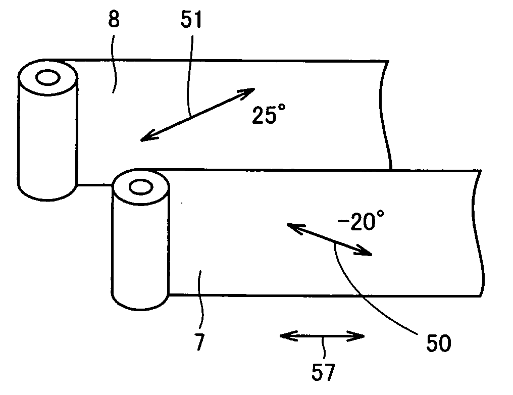
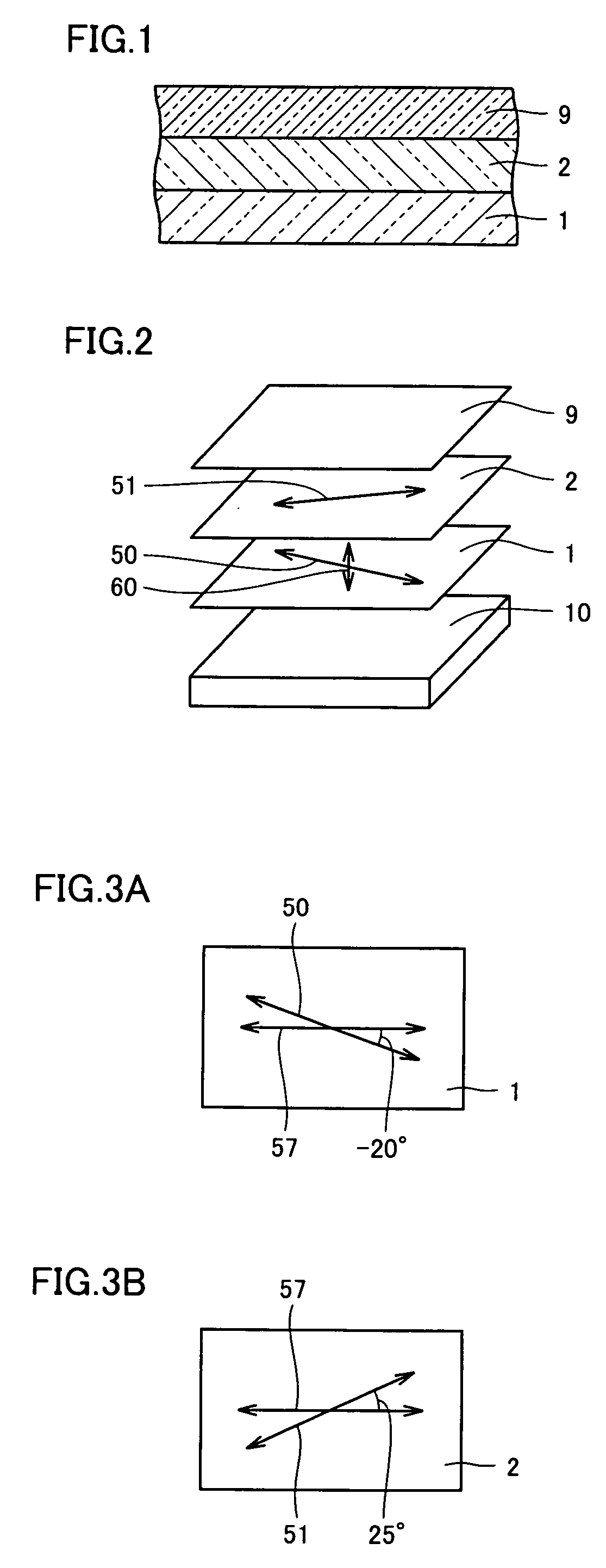
[0096] Referring to FIGS. 1 to 8B, description will now be given on a circularly polarizing plate and a vertical alignment type of liquid crystal display panel of a first embodiment according to the invention. A single or individual liquid crystal display unit included in a liquid crystal display panel of this embodiment is substantially the same as the individual liquid crystal display unit shown in FIG. 27. Thus, liquid crystal 23 fills a space surrounded by a substrate 20 on the display side, a substrate 21 on the opposite side and a seal member 22. Substrate 20 is provided with electrodes 24, and substrate 21 is provided with electrodes 25.

[0097] For example, when the liquid crystal display panel is a color liquid crystal display panel, one of the substrates (i.e., substrate 20) is e.g., a so-called color filter substrate. The color filter substrate is provided with a color filter layer (not shown) having hues of RGB. Electrode 24 is a transparent electrode made of, e.g., ITO (...

second embodiment

[0135] Referring to FIGS. 17 to 20, description will now be given on a circularly polarizing plate and a vertical alignment type of liquid crystal display panel of a second embodiment according to the invention. An individual liquid crystal display unit included in the liquid crystal display panel of this embodiment is substantially the same as the individual liquid crystal display unit shown in FIG. 27. More specifically, liquid crystal 23 fills a space sealingly surrounded by substrate 20 on the display side, substrate 21 on the other side opposite to the display side and seal member 22. Substrate 20 is provided with electrodes 24, and substrate 21 is provided with electrodes 25.

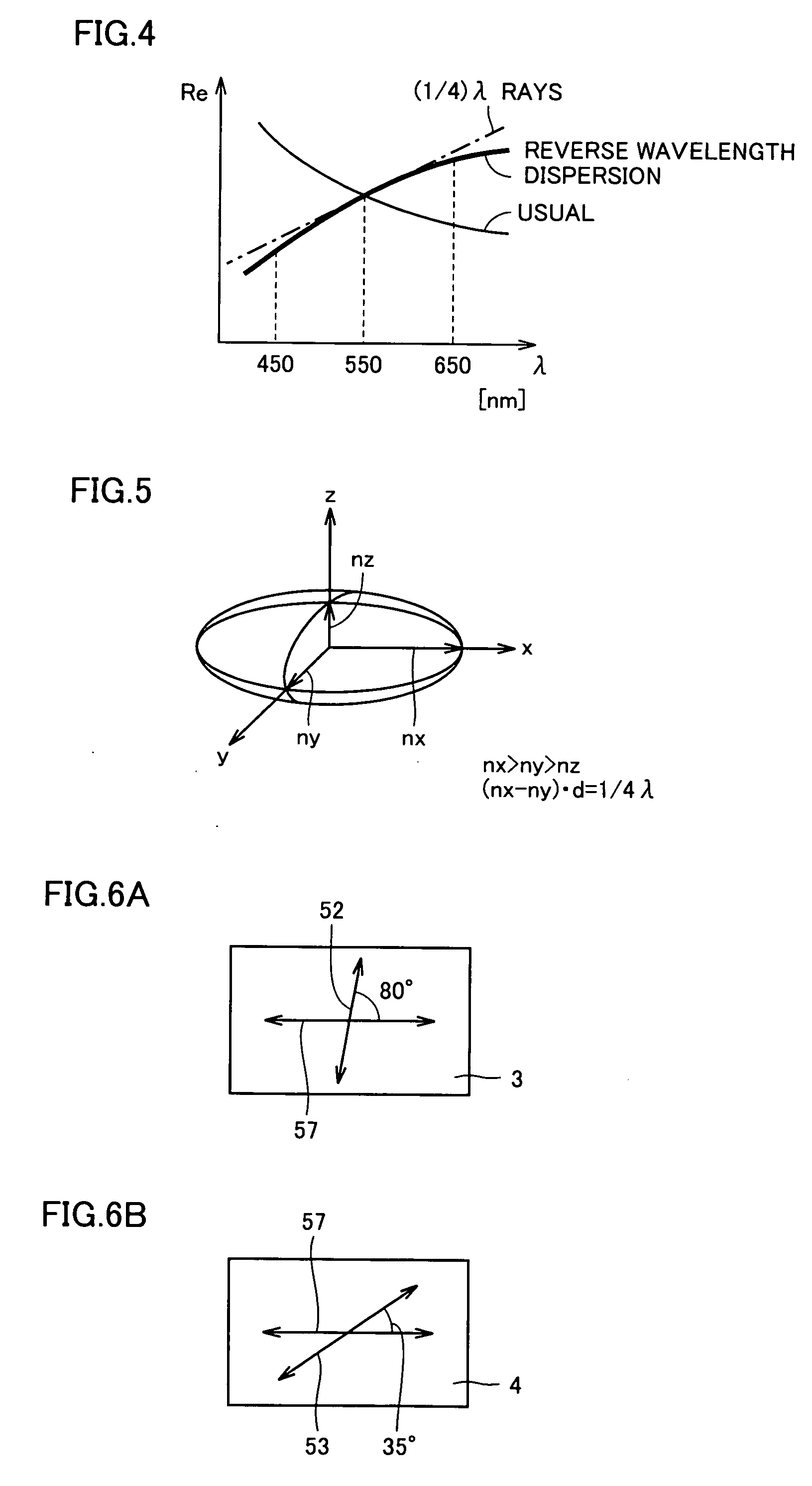
[0136] The liquid crystal display panel of this embodiment is of the vertical alignment type. This liquid crystal display panel employs a circularly polarizing plate formed of a linearly polarizing plate and a λ / 4 phase difference plate adhered together. The circularly polarizing plate has a function of c...


PUM

PropertyMeasurementUnit
angleaaaaaaaaaa
angleaaaaaaaaaa
angleaaaaaaaaaa

Abstract

A circularly polarizing plate includes a λ / 4 phase difference plate and a linearly polarizing plate overlaid on a main surface of the λ / 4 phase difference plate and having an absorption axis forming an angle of about 45° with respect to a lagging axis of the λ / 4 phase difference plate. The λ / 4 phase difference plate has reverse wavelength dispersion characteristics and an Nz coefficient of 1.6 or more. Employment of this structure can provide the circularly polarizing plate having good view angle characteristics and a vertical alignment type of liquid crystal display panel having the same.

Description

TECHNICAL FIELD [0001] The present invention relates to a circularly polarizing plate, a vertical alignment type of liquid crystal display panel and a method of manufacturing the same. BACKGROUND ART [0002] A liquid crystal display panel has two substrates between which liquid crystal is sealingly stored, and electrodes are formed on main surfaces of the substrates opposed together. [0003]FIG. 27 is a schematic cross section of a liquid crystal display panel. Electrodes 24 are formed on a substrate 20 on a display side, and electrodes 25 are formed on an opposite substrate 21. Substrates 20 and 21 are adhered together by a seal member 22 with electrodes 24 and 25 opposed to each other. Spacers (not shown) keep a constant distance between substrates 20 and 21. A region surrounded by two substrates 20 and 21 and seal member 22 is sealingly filled with liquid crystal 23. In the present invention, a structure that includes liquid crystal sealingly stored between the two substrates, and ...

Claims


Application Information

Patent Timeline
Patent Type & Authority Applications(United States)
IPC IPC(8): C09K19/00G02B5/30G02F1/13363G02F1/139
CPCG02B5/3083Y10T428/1041G02F2001/133638G02F1/1393C09K2323/031G02F1/133638G02B5/30G02F1/133
Inventor USUKURA, NARUABIRU, MANABUNATSUME, TAKAYUKIYAMABUCHI, KOJINAKAHARA, MAKOTO
Owner SHARP KK
Why Eureka
Try Eureka