Insertion device
a technology of insertion device and insertion tube, which is applied in the field of insertion device, can solve the problems of intestine deformation, surgeons are at risk of mistaking the insertion direction, and taking time in insertion,
- Summary
- Abstract
- Description
- Claims
- Application Information
AI Technical Summary
Benefits of technology
Problems solved by technology
Method used
Image

Examples
first embodiment
[0095] an insertion device will be described with reference to FIG. 1 through FIG. 6.
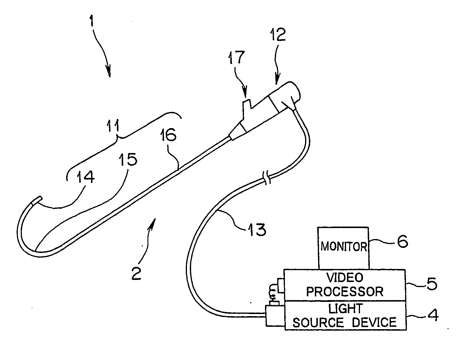
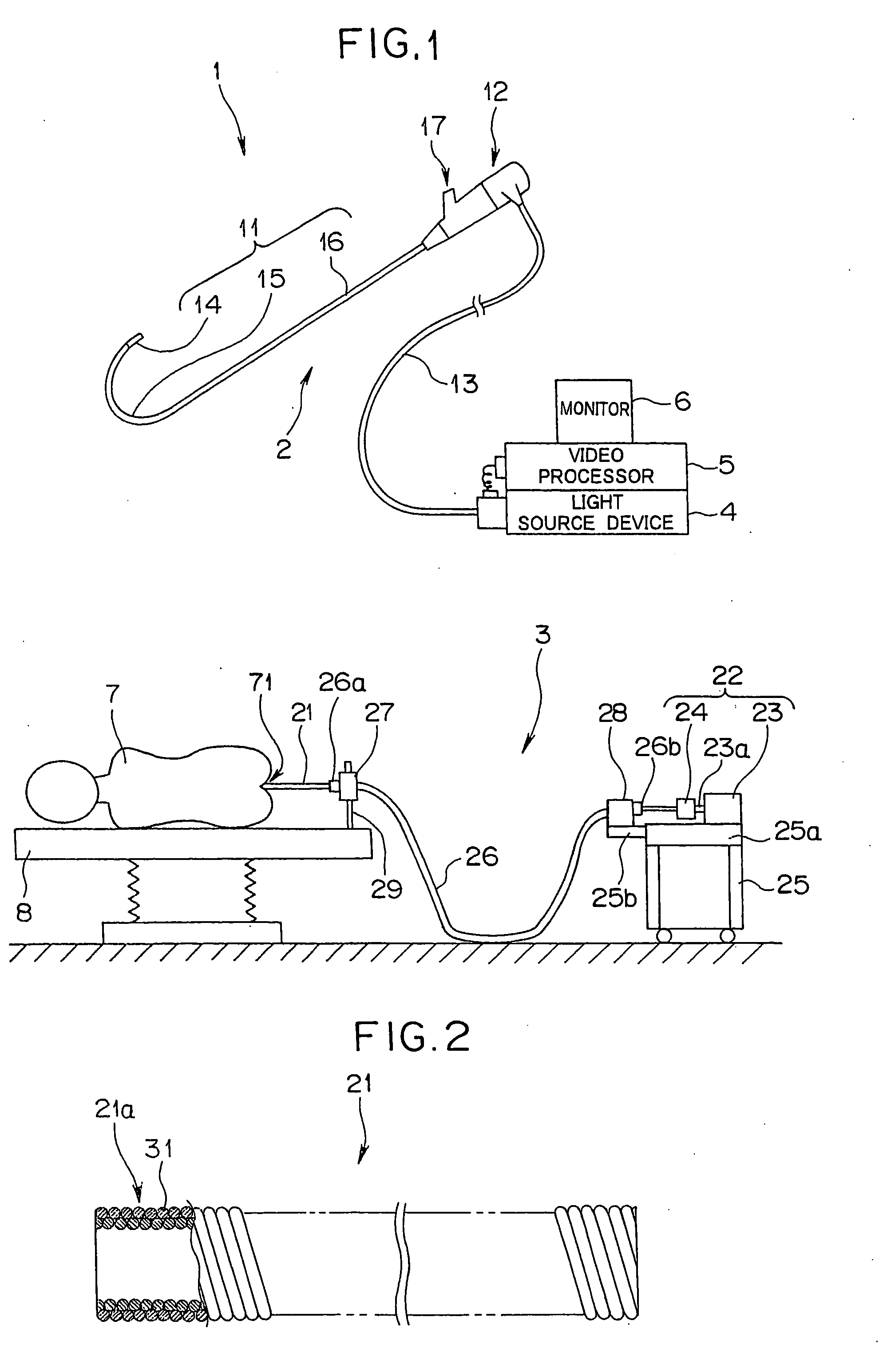
[0096] As illustrated in FIG. 1, an insertion device 1 according to the present embodiment principally comprises an endoscope 2 serving as medical equipment, and an endoscope insertion assisting tool 3.
[0097] The endoscope 2 is an observation device, and comprises an insertion unit 11, an operating unit 12, and a universal cord 13. The insertion unit 11 is long, and has a length of 500 mm or longer for example. The operating unit 12 is provided at the base side of the insertion unit 11. The universal cord 13 extends from the side portion of the operating unit 12.
[0098] The insertion unit 11 is configured so as to serially provide a tip rigid portion 14, a bending portion 15, and a flexible tube portion 16 in order from the tip side thereof. The bending portion 15 is configured so as to bend in the vertical and horizontal directions for example. The flexible tube portion 16 has flexibility. The ope...
second embodiment
[0141] an insertion device will be described with reference to FIG. 17 through FIG. 28.
[0142] The configuration of the insertion device according to the present embodiment is generally the same configuration as the above first embodiment, but a configuration wherein a tip guide member is provided at the tip side of an insertion-unit guide member is different from the first embodiment. Accordingly, with regard to generally the same configuration as the above first embodiment, drawings and detailed description thereof will be omitted, and description will be made below regarding only different members.
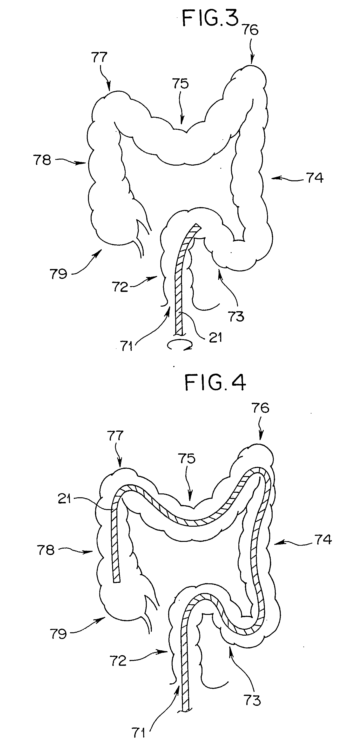
[0143] Description will be made regarding the configuration of the guide tube 21 including a tip guide member with reference to FIG. 17.
[0144] As illustrated in the drawing, the guide tube 21 is a spiral tube in which flexibility is considered, and is formed by winding a metal wire 31 in a spiral manner so as to form two layers. Accordingly, the outer surface of the guide tube 21 is pr...
third embodiment
[0172] an insertion device will be described with reference to FIG. 29 through FIG. 35.
[0173] The configuration of an insertion device according to the present embodiment is generally the same configuration as the above second embodiment, but the configuration of the tip guide member provided at the tip side of the insertion-unit guide member is slightly different from the second embodiment. Accordingly, with regard to the same configuration as the above first embodiment, drawings and detailed description thereof will be omitted, and description will be made below regarding only different members.
[0174] As illustrated in FIG. 29, the tip of the guide tube 21 according to the present embodiment is attached with the wire member 51. With this wire member 51, multiple, here, five guiders 50A are provided. The five guiders 50A are provided with a through hole passing through center thereof The through holes are inserted with the wire member 51. The diameter dimension of the through hole...
PUM
 Abstract
Description
Claims
Application Information
 - R&D
- Intellectual Property
- Life Sciences
- Materials
- Tech Scout
- Unparalleled Data Quality
- Higher Quality Content
- 60% Fewer Hallucinations
Browse by: Latest US Patents, China's latest patents, Technical Efficacy Thesaurus, Application Domain, Technology Topic, Popular Technical Reports.
© 2025 PatSnap. All rights reserved.Legal|Privacy policy|Modern Slavery Act Transparency Statement|Sitemap|About US| Contact US: help@patsnap.com