Needle insertion device

Active Publication Date: 2007-03-08
ARKRAY INC
View PDF16 Cites 83 Cited by
  • Summary
  • Abstract
  • Description
  • Claims
  • Application Information

AI Technical Summary

Benefits of technology

[0005] An object of the present invention is to provide a lan

Problems solved by technology

Therefore, on puncturing, the impact due to the collision of the engaging pin 97 and the end of the groove 96 is transmitted to the skin, and the impact causes pain and discomfort, an

Method used


Image

  • Needle insertion device
  • Needle insertion device
  • Needle insertion device

Examples


first embodiment

[0042] the present invention is described with reference to FIGS. 1-8.

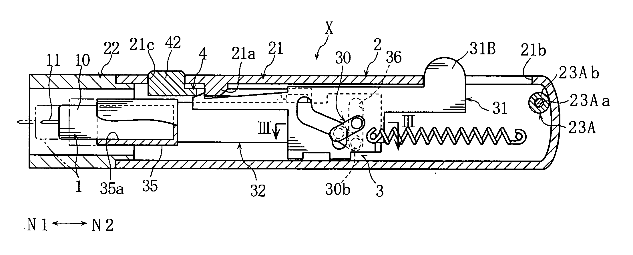
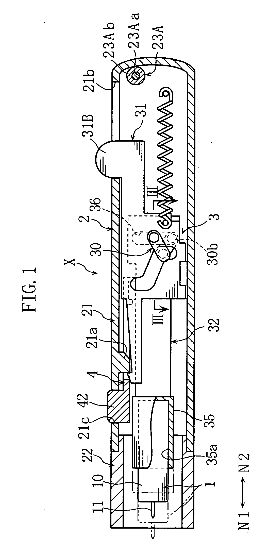
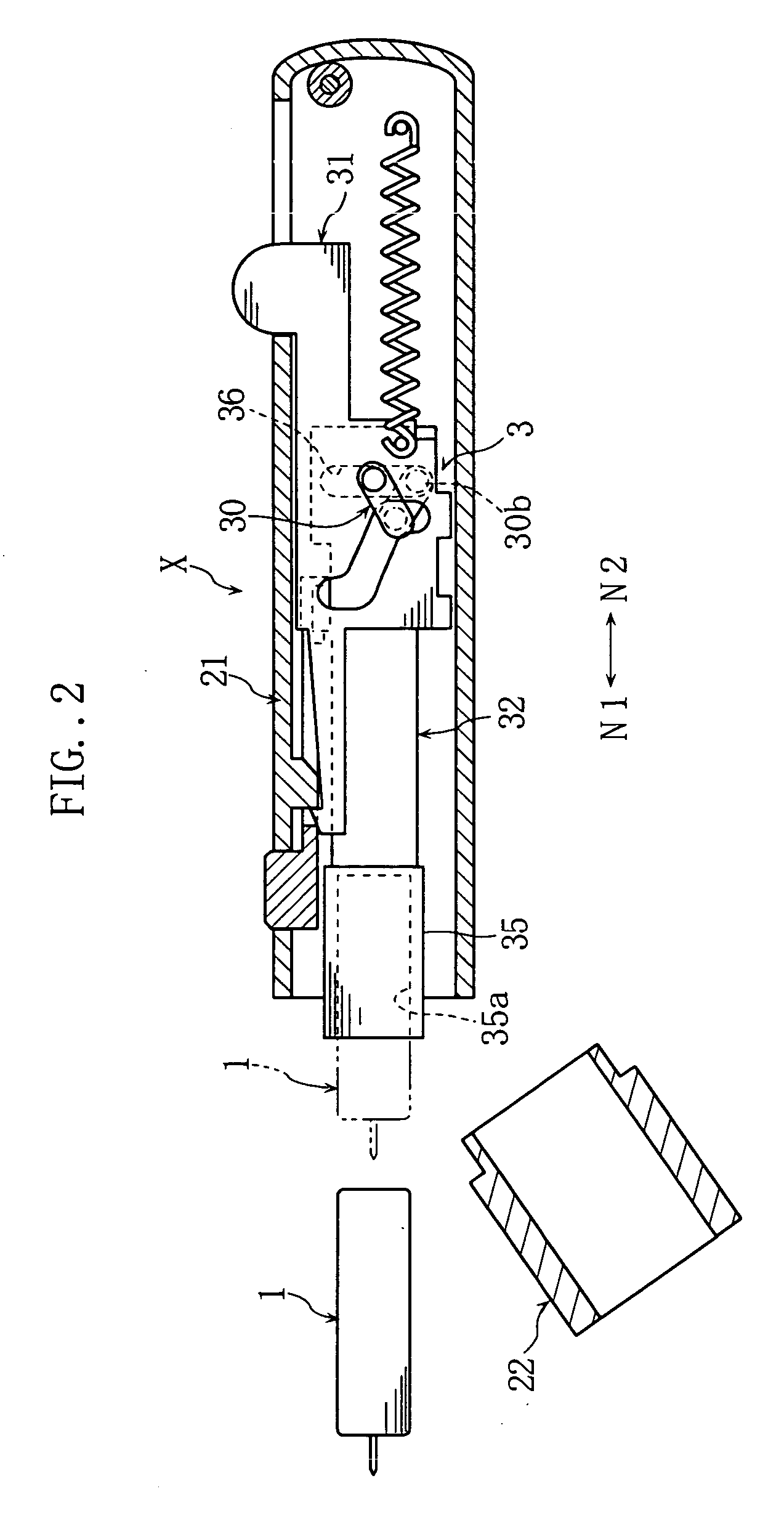
[0043] As shown in FIG. 1, a lancing device X is used for puncturing skin to cause bleeding therefrom, by moving a lancet 1 from a standby position (where the lancet 1 is illustrated by solid lines in the figure) to a puncturing position (where the lancet 1 is illustrated by phantom lines in the figure). The lancing device X includes a housing 2, a lancet moving mechanism 3, and a latch-releasing member 4.

[0044] The above-described lancet 1 for puncturing the skin is held in a lancet holder 32 which will be described later, and moves integrally with the lancet holder 32. The lancet 1 includes a body 10 and a lancing needle 11 protruding from the body, and is disposable, for example. The body 10 is tubular and made of a resin, for example. The lancing needle 11 is made of e.g. metal, and is integrated to the body 10 by insert molding. The lancing needle 11 of the lancet 1 may also adhere to the body 10.

[0045] The...


PUM


Abstract

A lancing device (X) comprising a first moving member (32) holding a lancing member (11) moved from a standby position to a puncturing position in a puncturing direction (N1), for puncturing a target portion by the lancing member (11). The lancing device (X) further comprises a second moving member (31) connected to the first moving member (32), for controlling the movement of the first moving member (32) upon the movement of the second moving member, and also comprises an impact absorbing means (23A) for absorbing impact that is caused when the first and the second moving members (31), (32) come to stop on puncture operation. The impact absorbing means (23A) includes an elastic member (23Ab) for absorbing impact by elastic deformation.

Description

TECHNICAL FIELD [0001] The present invention relates to a lancing device that punctures skin by a lancing member to obtain a sample of blood or a tissue. BACKGROUND ART [0002] An example of the lancing device utilizes a cam mechanism for sticking a lancet into skin (refer to JP-U-64-42010, for example). As shown in FIGS. 15A-15C, the lancing device disclosed in JP-U-64-42010 includes a cam 90 whose rotation is transformed into a reciprocal movement of a lancet supporting portion 91, so that a lancet 92 is moved together with the lancet supporting portion 91 to puncture the skin. [0003] As shown in FIG. 15A, in a standby position of the lancing device 9, the cam 90 is fixed with an urged coil spring 93. A pivot lever 94 is operated to disengage the fixation of the cam 90, as shown in FIGS. 15B and 15C. Then, the cam 90 rotates about a shaft 95. The cam 90 is formed with a v-shaped groove 96, and the groove 96 engages an engaging pin 97 that is formed integral with the lancet supporti...

Claims


Application Information

Patent Timeline
IPC IPC(8): A61B17/32A61B5/151A61B5/15
CPCA61B5/15186A61B5/1411A61B5/150022A61B5/150412A61B5/15113A61B5/15117A61B5/15128A61B5/1519A61B5/15194
Inventor FUKUZAWA, MASHIROUEHATA, YOSHIHARU
Owner ARKRAY INC
Why Eureka
Try Eureka