
Dishwasher comprising a circulating pump

a technology of circulating pump and dishwasher, which is applied in the field of dishwasher, can solve the problems of increasing the height of spray jets at individual nozzles, and achieve the effect of being inexpensive and simpl

Inactive Publication Date: 2007-03-15
MIELE & CO KG
View PDF1 Cites 46 Cited by
  • Summary
  • Abstract
  • Description
  • Claims
  • Application Information

AI Technical Summary

Benefits of technology

[0005] It is, therefore, an object of the present invention to provide an inexpensive and simple switching device which can be used to enable the flow path to one or the other group of spray nozzles.
[0007] A means which enables either one or the other group of spray nozzles of a nozzle arm for the wash water in a random manner and independently of the control system is disposed in the area of the nozzle arm, thereby providing that sub-areas of the spray arm are supplied with wash water at random. Thus, the volume flow available is passed through a small number of nozzles, resulting in an increase in the spray jet height at the individual nozzles. In addition, due to the distribution of the volume flow, the total amount of circulated water is smaller, which saves water. The means that arbitrarily controls the volume flow of the wash water is advantageously disposed in the axis of rotation of the nozzle arm and, more precisely, in the wash water supply conduit. This design eliminates the need for additional supply paths or means for supplying wash water to the individual groups of spray nozzles. In addition, a design of this type does not need a diverting device or any additional pumps to be accommodated in the housing.

Problems solved by technology

Thus, the volume flow available is passed through a small number of nozzles, resulting in an increase in the spray jet height at the individual nozzles.

Method used


Image

  • Dishwasher comprising a circulating pump
  • Dishwasher comprising a circulating pump
  • Dishwasher comprising a circulating pump

Examples


Embodiment Construction

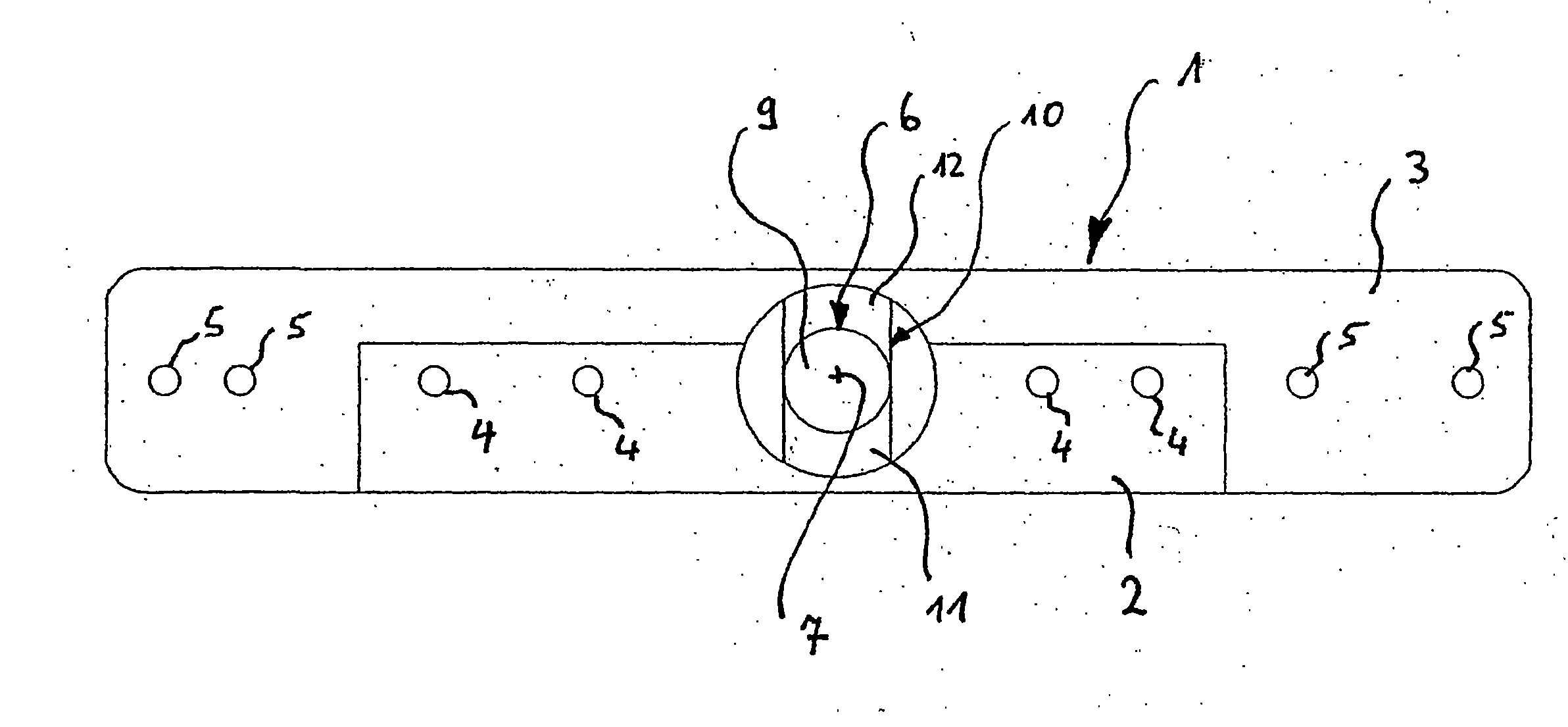
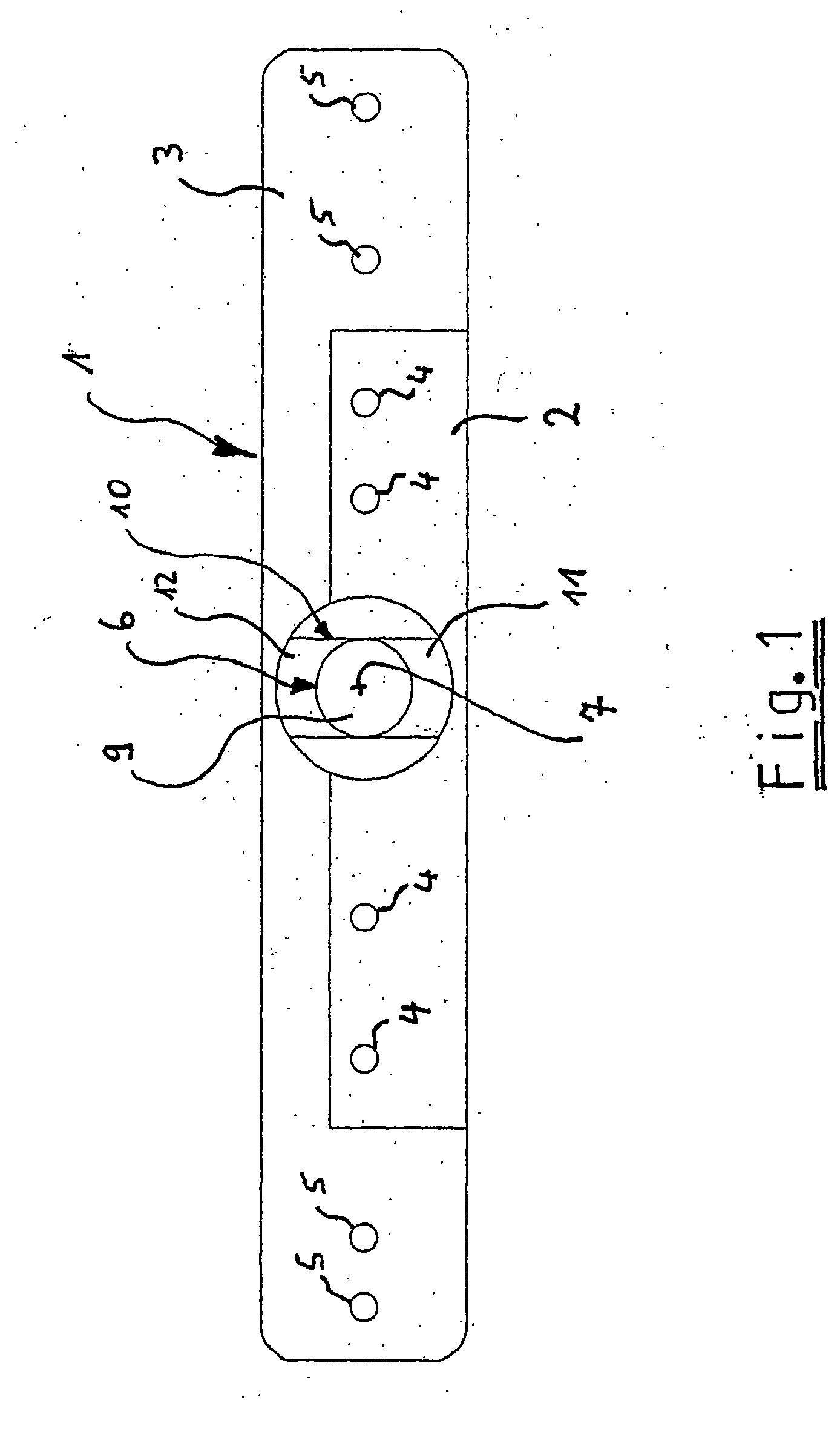
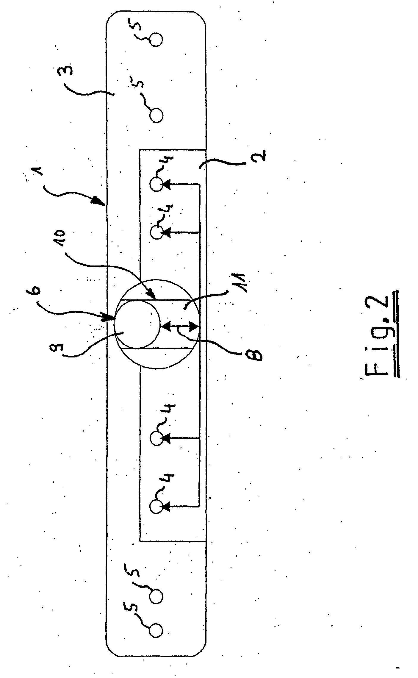
[0014] The isolated top views of FIGS. 1 through 3 each show a nozzle arm 1 on which are arranged two groups 2 and 3 of spray nozzles 4 and 5.

[0015] Groups 2 and 3 of spray nozzles 4 and 5 are operated independently by wash water flowing through them. As is apparent when viewing FIGS. 1 through 3 together, a means 6 is disposed in the area of nozzle arm 1, said means enabling either the one group 2 (FIG. 2) or the other group 3 (FIG. 3) of spray nozzles 4 or 5 of nozzle arm 1 for the wash water in a random manner and independently of the control system. As can be seen from FIGS. 2 and 3, the nozzles indicated by arrows according to the position of means 6 are enabled, respectively.

[0016] As can be seen from FIG. 1, means 6 is disposed in axis of rotation 7 of nozzle arm 1. More precisely, means 6 is disposed in the wash water supply conduit, which is also provided in axis of rotation 7 of nozzle arm 1.

[0017] When viewing FIGS. 1 through 3 together, in particular with respect to a...


PUM


Abstract

A dishwasher includes a circulating jump, a spraying system and a spray nozzle enabling device. The spraying system is disposed in a spray chamber and includes a first and a second group of spray nozzles, the first and second group of spray nozzles being disposed on a rotatable nozzle arm. The first and second group of spray nozzles are capable of being operated independently by wash water flowing therethrough. The spray nozzle enabling device is disposed in an area of the nozzle arm and configured to enable, for the wash water, alternately either the first or the second group of spray nozzles in a random manner and independently of a control system associated with the spraying system.

Description

CROSS-REFERENCE TO PRIOR APPLICATION [0001] The above-referenced application is the U.S. National Phase of International Patent Application PCT / EP2004 / 012926, filed Nov. 15, 2004, which claims priority from German Application No. 103 55 343.6, filed Nov. 25, 2003, which is incorporated by reference herein. The International application was published in German on Jun. 30, 2005 as WO 2005 / 058123 A1.BACKGROUND [0002] The present invention relates to a dishwasher comprising a circulating pump and at least one spraying system provided in the wash chamber and having at least two groups of spray nozzles provided on a rotatably mounted nozzle arm, said groups of spray nozzles being able to be operated independently by fluid flowing through them. [0003] Spraying systems intended for use in dishwashers and having nozzle arms provided with channels which are arranged separately from each other and are respectively equipped with nozzle openings are sufficiently known from the prior art. The noz...

Claims


Application Information

Patent Timeline
IPC IPC(8): B08B3/00A47L15/23A47L15/42
CPCA47L15/4282A47L15/23
Inventor HAAS, ANDREASLAGHUSEMANN, JENS
Owner MIELE & CO KG
Learn More