Pleated blind having positioning function

Inactive Publication Date: 2007-03-15
LIN YA YIN
View PDF2 Cites 5 Cited by
  • Summary
  • Abstract
  • Description
  • Claims
  • Application Information

AI Technical Summary

Benefits of technology

[0008] A further objective of the present invention is to provide a pleated blind, wherein each of the pleated portions of the blind body will not be opened excessively due to improper operation of the lift cord by a user, thereby preventing either one of the pleated portions of the blind body from be

Problems solved by technology

However, when a user exerts an excessive force on the lift cord 8, some of the pleated portions 61 of the blind body 6 are opened excessively due to improper operation of the lift cord 8 by th

Method used


Image

  • Pleated blind having positioning function
  • Pleated blind having positioning function
  • Pleated blind having positioning function

Examples


Example

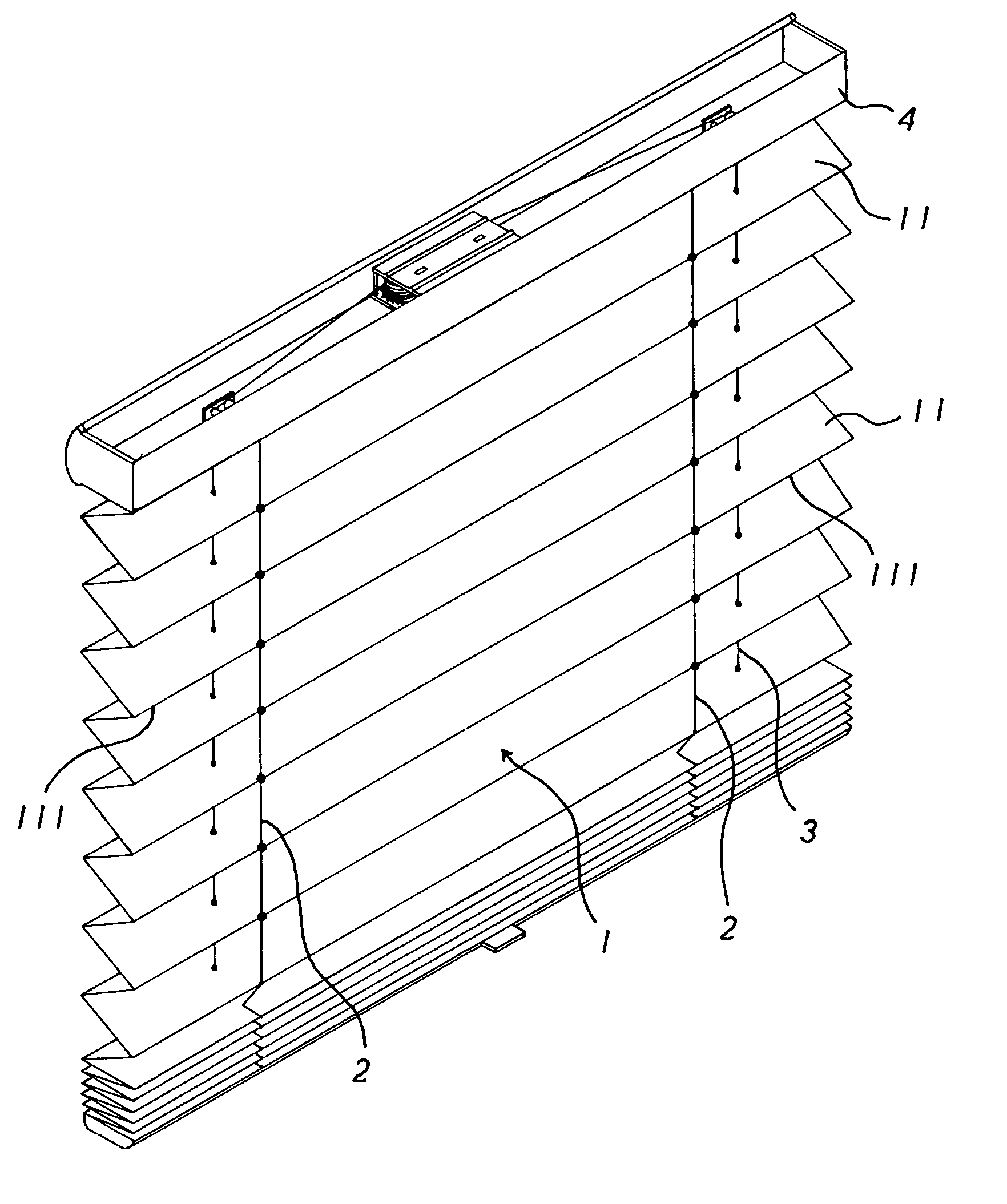
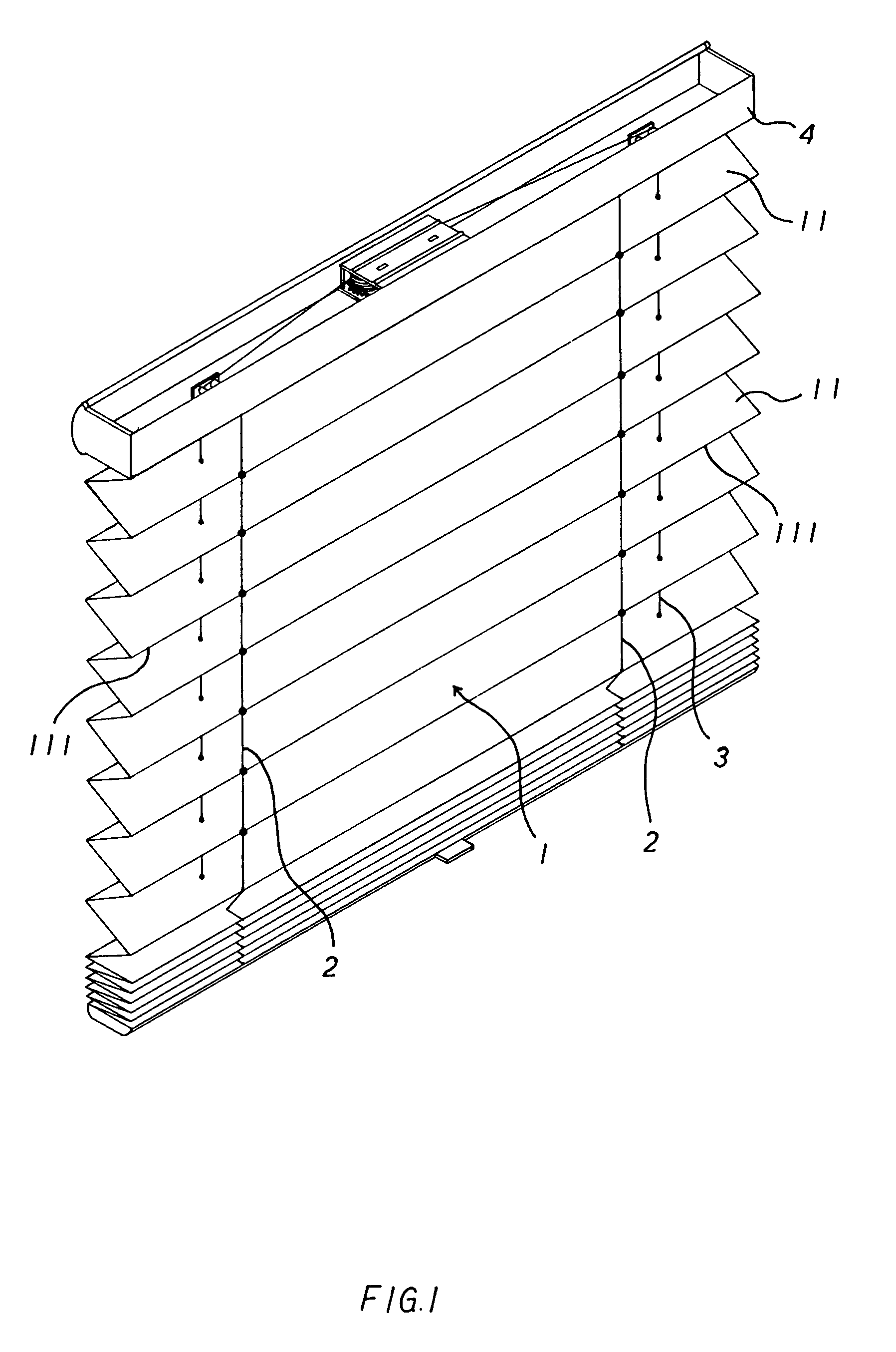
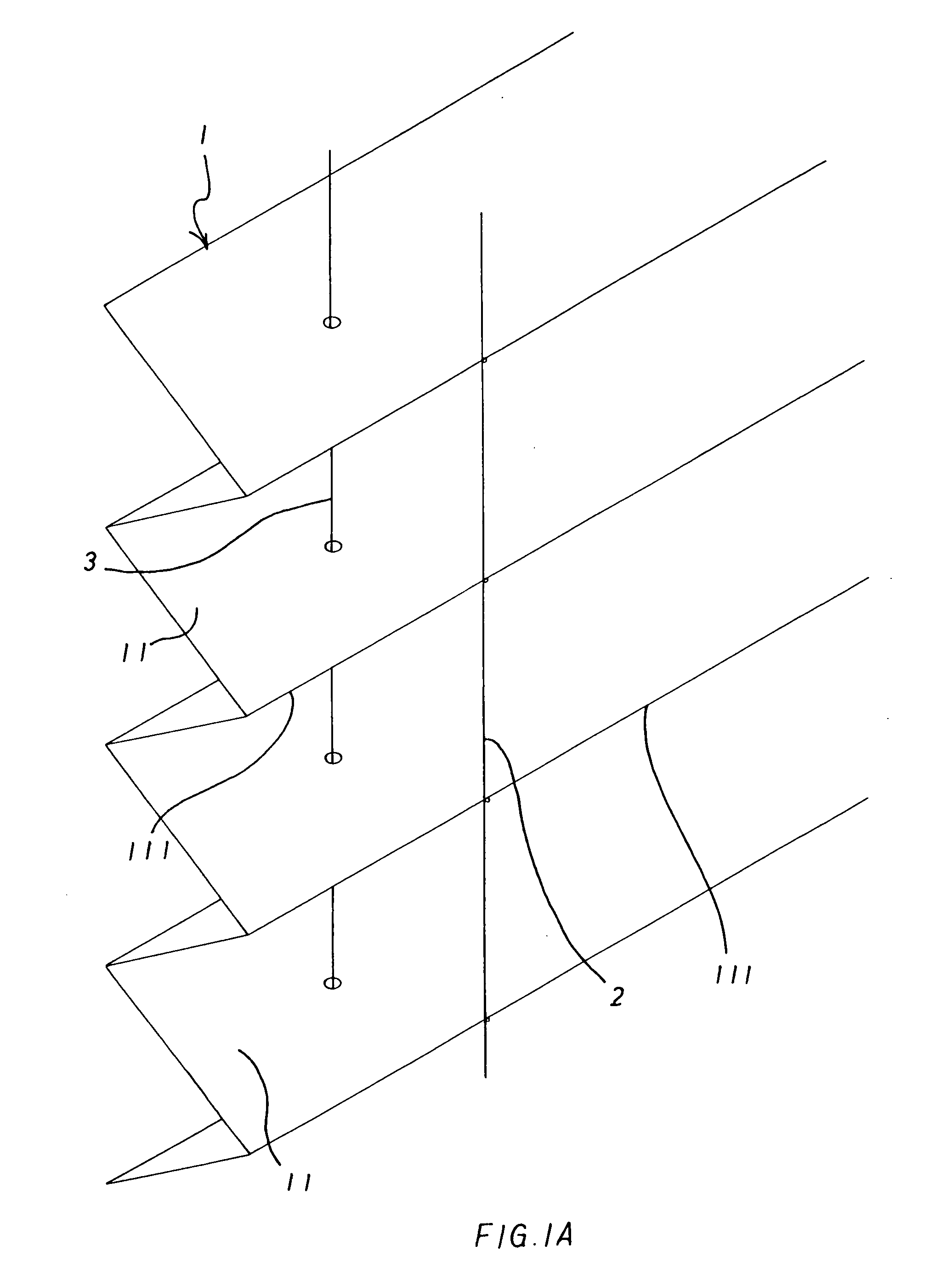
[0019] Referring to the drawings and initially to FIG. 1, a pleated blind in accordance with the preferred embodiment of the present invention comprises a headrail 4, a blind body 1 mounted on the headrail 4 and having a plurality of pleated portions 11 each having a pleated edge 111, a lift cord 3 extended through the headrail 4 and each of the pleated portions 11 of the blind body 1 to control upward and downward movement of the blind body 1, and a limit cord 2 secured to the pleated edges 111 of some of the pleated portions 11 of the blind body 1 to limit a distance between the pleated edges 111 of the pleated portions 11 of the blind body 1.

[0020] Preferably, the limit cord 2 is secured to the pleated edge 111 of each of the pleated portions 11 of the blind body 1 to limit a distance between any two adjacent pleated edges 111 of the pleated portions 11 of the blind body 1.

[0021] In addition, the pleated edge 111 of an uppermost one of the pleated portions 11 of the blind body ...


PUM


Abstract

A pleated blind includes a blind body having a plurality of pleated portions each having a pleated edge, and a limit cord secured to the pleated edges of the pleated portions of the blind body. When the pleated portions are moved, the maximum distance between any two adjacent pleated edges of the pleated portions is limited by the limit cord, so that the open distance of each of the pleated portions is limited by the limit cord to reach a determined value. Thus, each of the pleated portions will not be opened excessively due to improper operation by a user, thereby preventing either one of the pleated portions from being deformed or distorted due to an overload so as to enhance the outer appearance of the pleated blind.

Description

BACKGROUND OF THE INVENTION [0001] 1. Field of the Invention [0002] The present invention relates to a pleated blind, and more particularly to a pleated blind having a positioning function. [0003] 2. Description of the Related Art [0004] A conventional pleated blind in accordance with the prior art shown in FIG. 6 comprises a headrail 7, a blind body 6 mounted on the headrail 7 and having a plurality of pleated portions 61, and a lift cord 8 extended through the headrail 7 and each of the pleated portions 61 of the blind body 6 to control upward and downward movement of the blind body 6. Each of the pleated portions 61 of the blind body 6 has a through hole 62 to allow passage of the lift cord 8. However, when a user exerts an excessive force on the lift cord 8, some of the pleated portions 61 of the blind body 6 are opened excessively due to improper operation of the lift cord 8 by the user, so that the pleated portions 61 of the blind body 6 are easily deformed or distorted due to...

Claims


Application Information

Patent Timeline
IPC IPC(8): A47H5/00
CPCE06B2009/2625E06B9/262
Inventor LIN, YA-YIN
Owner LIN YA YIN
Why Eureka
Try Eureka