Autoreaming systems and methods

a technology of auto-reaming and system, which is applied in the direction of shaft equipment, borehole/well accessories, survey, etc., can solve the problems of drill string becoming overtorqued, bit is prone to damage, and bit may be damaged

Active Publication Date: 2007-03-15
VARCO I P INC
View PDF48 Cites 18 Cited by
  • Summary
  • Abstract
  • Description
  • Claims
  • Application Information

AI Technical Summary

Benefits of technology

[0013] The present invention discloses, in at least certain aspects, methods for controlling movement of a bit of a drilling assembly during reaming of a hole; the method, in one aspect, including determining a speed for downward movement of the bit, moving the bit downward in a hole at said speed, determining a time period for deceleration of the downwardly moving bit as it approaches the hole bottom, determining a value for a target parameter related to the reaming of the hole to be achieved as the bit comes down to the bottom of the hole, decelerating the movement of the bit for the time period, and ending the period when the value is achieved at the bottom of the hole. “Reaming” includes moving a drillstring with a bit down into an already-drilled hole to advance the bit to the bottom of the hole whether additional widening of the already-drilled hole is accomplished or not by the downwardly advancing bit and whether or not the bit is rotating. The present invention discloses systems for and computer readable mediums programmed to effect such methods.

Problems solved by technology

During the initial part of a drilling operation, the bit is prone to damage.
If setting down and rotation is begun too quickly, the bit may be damaged by the suddenness of the contact with the rock, or the drill string may become overtorqued.
If setting down and rotation are done too slowly, rig time is wasted.
This may be counterproductive.
Attempting to achieve the setpoint quickly may cause a step-change to the system that results in damage to the bit, overtorquing of the drill string and other problems.
Pinckard's system, however, does not attempt to solve the problems associated with the start of drilling or drilling in of a bit.

Method used


Image

  • Autoreaming systems and methods
  • Autoreaming systems and methods
  • Autoreaming systems and methods

Examples


Embodiment Construction

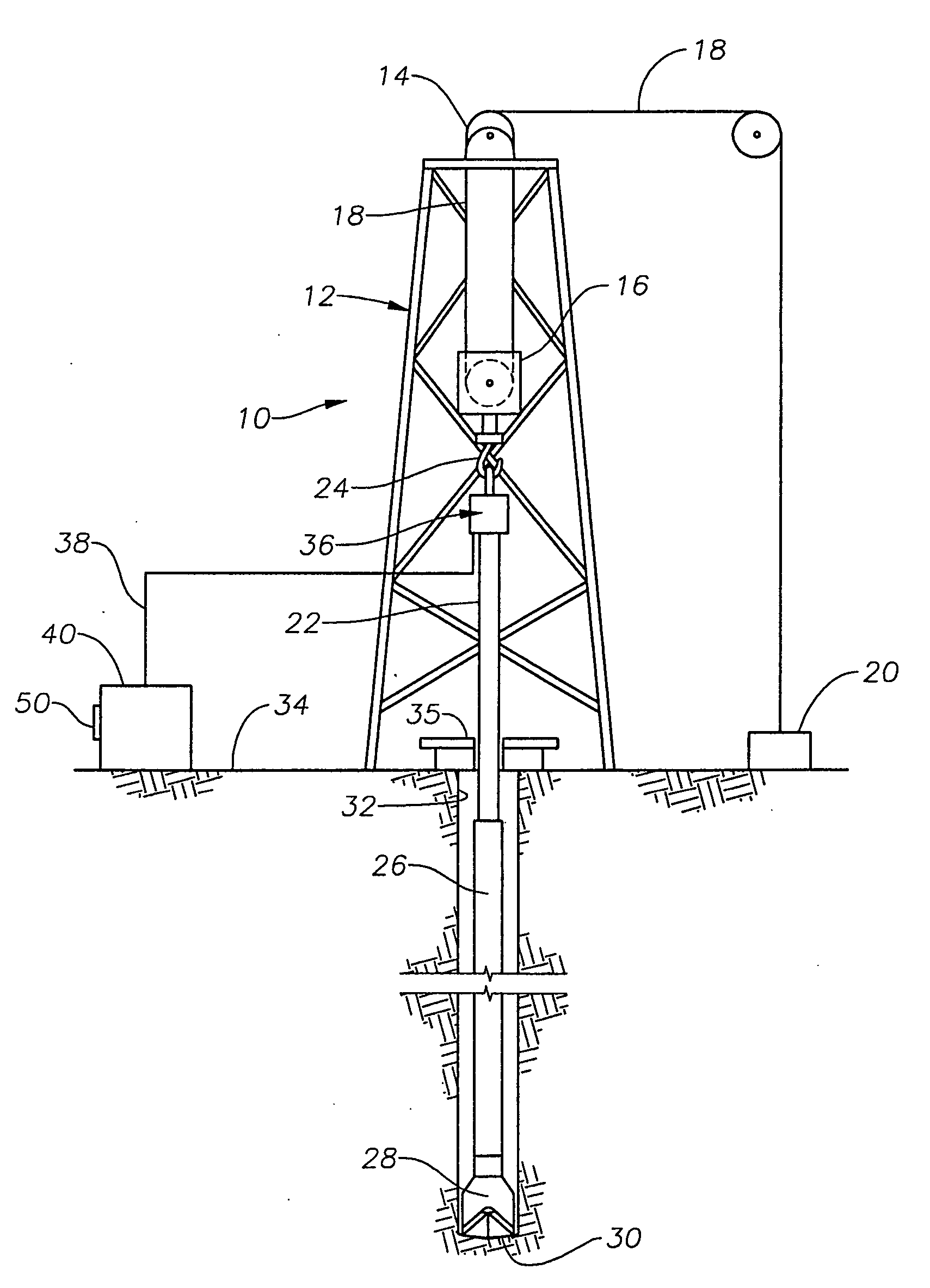
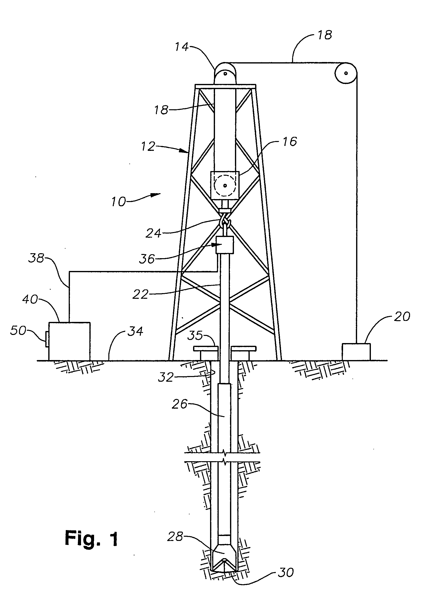
[0045]FIG. 1 illustrates, in schematic fashion, an exemplary drilling rig 10 with an automatic drilling system. The rig 10 includes a supporting derrick structure 12 with a crown block 14 at the top. A traveling block 16 is movably suspended from the crown block 14 by a cable 18, which is supplied by draw works 20. A kelly 22 is hung from the traveling block 16 by a hook 24. The lower end of the kelly 22 is secured to a drill string 26. The lower end of the drill string 26 has a bottom hole assembly 28 that carries a drill bit 30. The drill string 26 and drill bit 30 are disposed within a borehole 32 that is being drilled and extends downwardly from the surface 34. The kelly 22 is rotated within the borehole 32 by a rotary table 35. Other features relating to the construction and operation of a drilling rig, including the use of mud hoses, are well known in the art and will not be described in any detail herein.

[0046] A load cell assembly, generally shown at 36, is disposed below t...


PUM


Abstract

Methods and systems for controlling movement of a bit of a drilling assembly during reaming of an already-drilled hole; the methods, in certain aspects, including determining a ream speed for downward movement of the bit in the hole, moving the bit downward in a hole at said ream speed, determining a time period for deceleration of the bit to the hole bottom, determining a value for a target drilling parameter for drilling beyond the bottom of the hole, decelerating the bit (linearly or non-linearly) for the time period, and achieving the value for the target drilling parameter when the bit reaches the bottom of the hole.

Description

CROSS-REFERENCE TO RELATED APPLICATION [0001] This is a continuation-in-part of U.S. application Ser. No. 10 / 745,247 filed on Dec. 23, 2003, issued as U.S. Pat. No. 7,100,708 on Sep. 05, 2006; all of said application and said patent are incorporated fully herein by reference for all purposes; and from and based on said application and said patent the present invention claims priority under the Patent Laws.BACKGROUND OF THE INVENTION [0002] 1. Field Of The Invention [0003] The invention relates generally to systems for drilling boreholes for the production of hydrocarbons. More particularly, the invention relates to devices and methods for protecting the bit during the initial stages of the drilling operation in order to extend the lifetime of the bit. [0004] 2. Description of Related Art [0005] To obtain hydrocarbons such as oil and gas, boreholes are drilled by rotating a drill bit attached at a drill string end. Modem drilling systems generally employ a drill string having a botto...

Claims


Application Information

Patent Timeline
Patent Type & Authority Applications(United States)
IPC IPC(8): E21D1/06E21B44/00
CPCE21B44/02E21B7/28
Inventor KOEDERITZ, WILLIAM LEOPORCHE, MICHAEL NATHANTHOMAS, C. RANDALL
Owner VARCO I P INC
Why Eureka
Try Eureka