Directional antenna structure
- Summary
- Abstract
- Description
- Claims
- Application Information
AI Technical Summary
Benefits of technology
Problems solved by technology
Method used
Image
Examples
Embodiment Construction
[0020] In order to further understand the technology content and the construction requirements disclosed in the present utility model, the present utility model is illustrated below with reference to the accompanied drawings. However, the accompanying drawings are used for reference and illustration, but not intended to limit the scope of the present utility model.
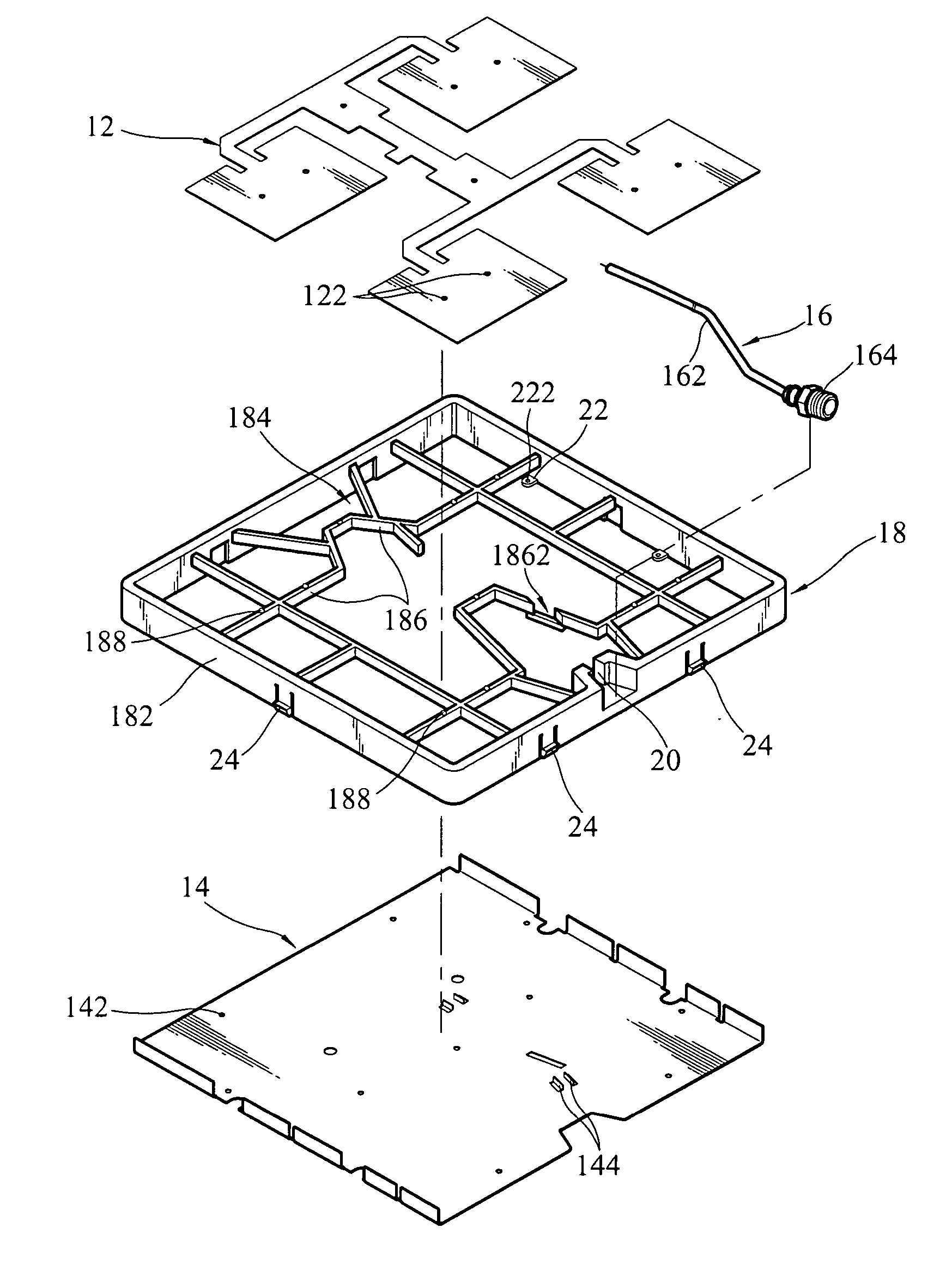
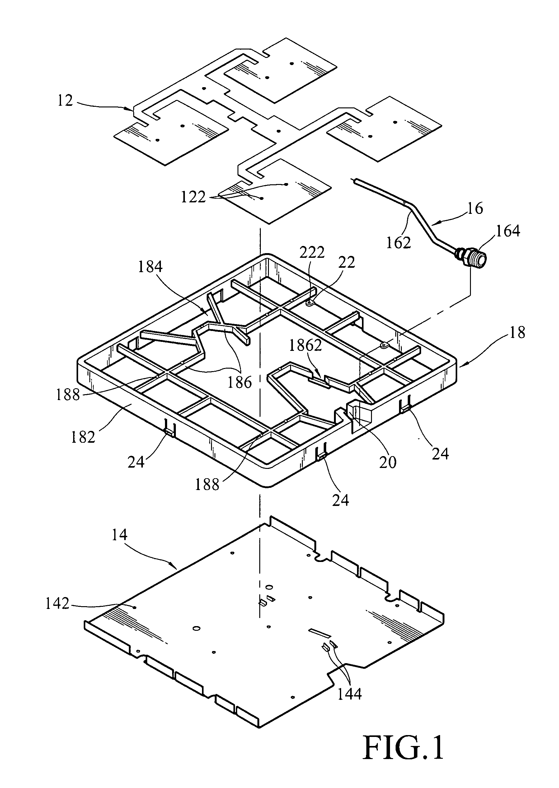
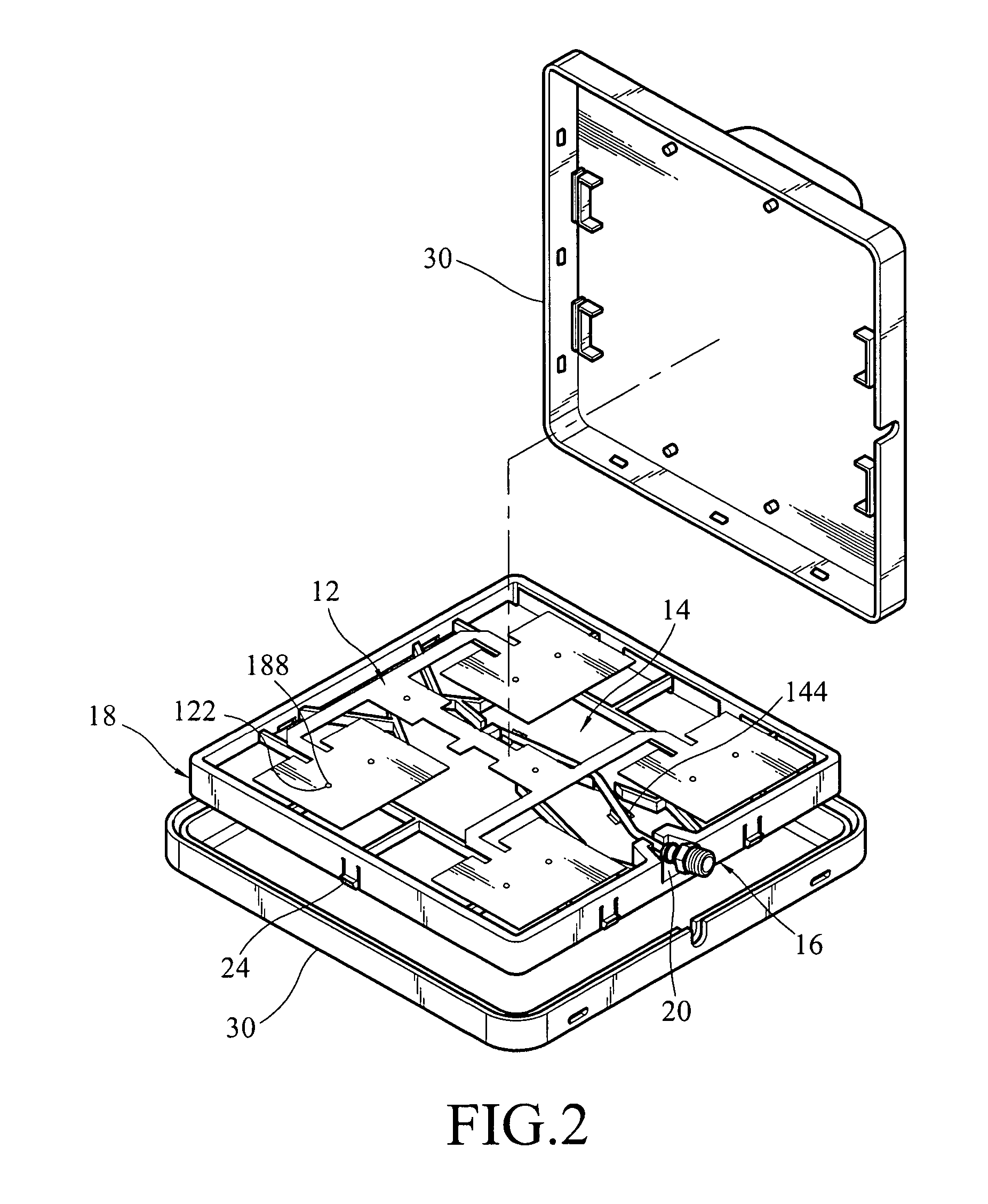
[0021]FIG. 1 is an exploded stereogram of an antenna structure, FIG. 2 is a stereogram after the antenna structure disclosed in FIG. 1 has been assembled, which shows a style of a housing that wraps and integrates with the antenna structure. As shown in the figures, the antenna structure comprises a patch antenna 12, a reflection plate 14, a cable connector 16, and a frame 18.
[0022] The frame 18 has an outside border 182 and a supporting rib 184 formed within the outside border 182, wherein the supporting rib 184 is formed by a plurality of connected ribs 186 that are connected with each other, and the quantity and conne...
PUM
 Abstract
Description
Claims
Application Information
 - R&D
- Intellectual Property
- Life Sciences
- Materials
- Tech Scout
- Unparalleled Data Quality
- Higher Quality Content
- 60% Fewer Hallucinations
Browse by: Latest US Patents, China's latest patents, Technical Efficacy Thesaurus, Application Domain, Technology Topic, Popular Technical Reports.
© 2025 PatSnap. All rights reserved.Legal|Privacy policy|Modern Slavery Act Transparency Statement|Sitemap|About US| Contact US: help@patsnap.com


