
Liquid crystal display device

a liquid crystal display and display device technology, applied in the direction of instruments, static indicating devices, etc., can solve the problems of low efficiency, achieve high light emission efficiency, low cost, and good color tone

Inactive Publication Date: 2007-03-15
TPO HONG KONG HLDG
View PDF3 Cites 1 Cited by
  • Summary
  • Abstract
  • Description
  • Claims
  • Application Information

AI Technical Summary

Benefits of technology

[0013] The present invention provides a driving circuit of a liquid crystal display device for obtaining an image without a tone reversal, having a satisfactory color tone, and a high light emitting efficiency. The present invention also provides a liquid crystal display device including the same driving circuit mentioned above.
[0015] In the liquid crystal display device according to the present invention, the tone voltage is supplied to the selected data line based on the tone data in the distributing part, and based on the tone voltage generating part, and the relationship between the optimum setting tone voltage and the tone data. Thus the liquid crystal display circuit without tone reversal, with satisfactory color tone and high light emitting efficiency is realized simply and at low cost without increase in the circuit space by combining the existing circuit elements. In particular, the tone voltage generating part and the distributing part are operated in time sharing thereby reducing an occupying area.

Problems solved by technology

Therefore, in the conventional liquid crystal display device, the cell thickness is reduced and slight dark with the lower luminance is used to prevent the tone reversal of the display screen, and thus the efficiency is low.

Method used


Image

  • Liquid crystal display device
  • Liquid crystal display device
  • Liquid crystal display device

Examples


first embodiment

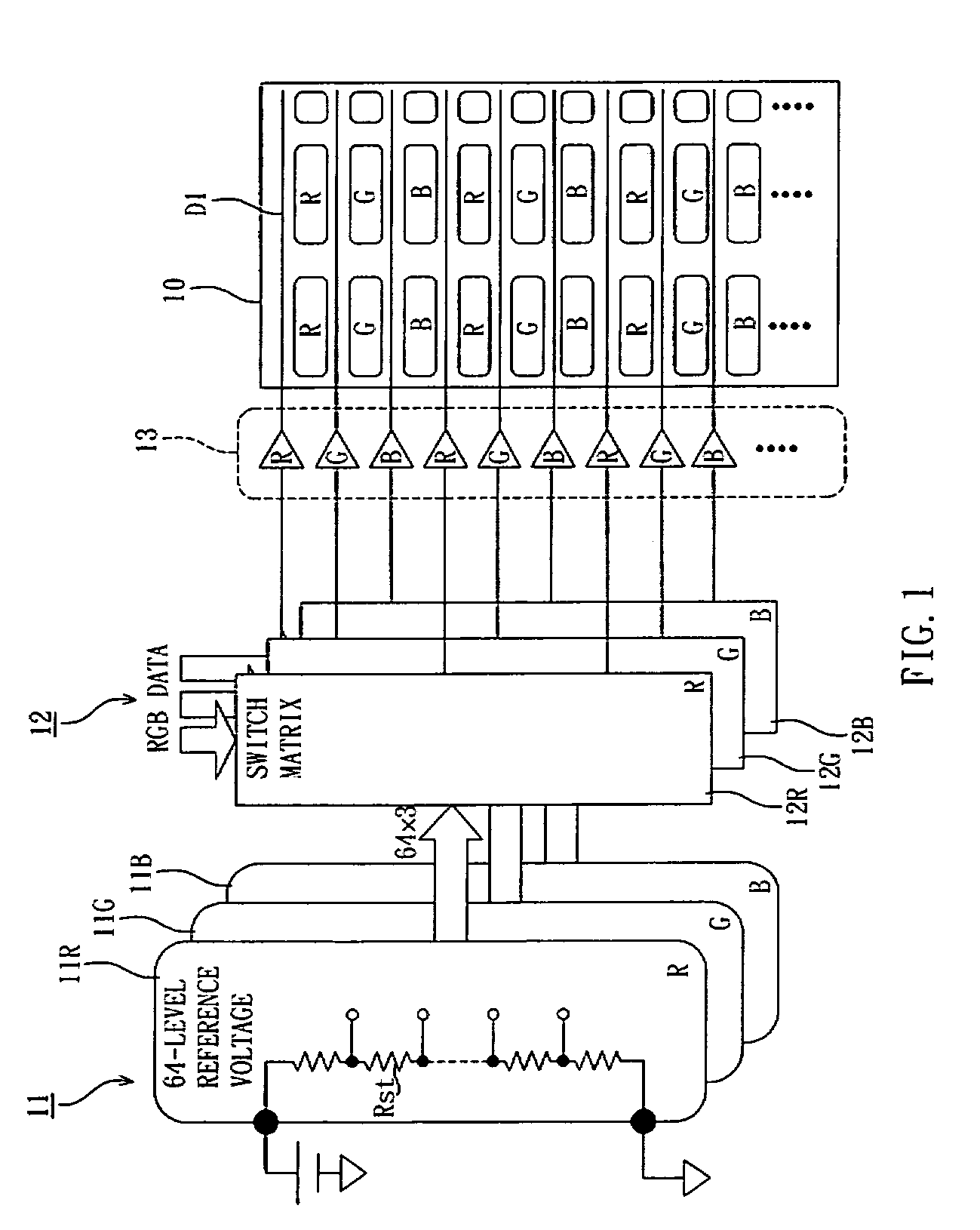
[0032] 192 lines are necessary for the connection between the tone voltage generating part 21 and the distributing part 12, and 192 lines are substantially not different from FIG. 1.

third embodiment

[0033]FIG. 3 shows a third embodiment in which the example of FIG. 2 is further modified.

[0034] In the present embodiment, a tone voltage generating part 31 retrieves 192 tones described in FIG. 2, but has a configuration of generating the tone voltage for each color in each at the three divided periods through time sharing in one data line selection period.

[0035] Therefore, although the tone voltage that can be outputted in 192 levels, 64 tones are outputted and sent to a distributing part 40 of the next stage in 64 lines.

[0036] Furthermore, since the tone to be outputted is 64, the tone that can be produced may be in 64 levels. Furthermore, since one tone voltage generating part is commonly used among each color through time sharing, the same tone voltage can be used for different colors.

[0037] The distributing part 40 includes a switch matrix 41, an analog buffer 42, and a switch 43. The switch matrix 41 selects the tone voltage corresponding to the tone from the inputted RGB ...


PUM


Abstract

The present invention provides a driving circuit of a liquid crystal display device for obtaining an image without tone reversal, having satisfactory color tone, and high light emitting efficiency; and a liquid crystal display device including the same. The liquid crystal display device includes a liquid crystal display element array for obtaining a desired tone display when a voltage corresponding to the tone is supplied through a selected data line, and the liquid crystal elements are arranged for each color of red, green, and blue in a matrix form; a tone voltage generating part for generating an analog voltage corresponding to all tones of three colors; and a distributing part for sending the voltage corresponding to the tone of data line to the data line according to tone data value from the correspondence relationship between the tone data value and a voltage corresponding to the tone generated at the tone voltage generating part.

Description

[0001] This application claims the benefit of Japan Patent Application Ser. No. 2005-263552, filed on Sep. 12, 2005. BACKGROUND OF THE INVENTION [0002] 1. Field of Invention [0003] The present invention relates to a liquid crystal display device and, in particular, to a driving circuit of a data line in a liquid crystal display device. [0004] 2. Related Art [0005] In an active matrix liquid crystal display device, a column driver selects a column line of the liquid crystal display element array so that a TFT is turned ON. Then, data related to the tone of each color is provided to a data line (a row line), and the transmissivity of the liquid crystal is changed to obtain a desired color according to the above-mentioned data. [0006] Conventionally, red (R), green (G), and blue (B) are applied with the same tone versus voltage curve so that the liquid crystal display device can control the change of the brightness from completely white to completely black. Herein, the voltage data cor...

Claims


Application Information

Patent Timeline
Patent Type & Authority Applications(United States)
IPC IPC(8): G09G3/36
CPCG09G3/3685G09G2320/0276G09G2320/0242G09G2310/0297
Inventor HASHIMOTO, KAZUYUKISHIBAZAKI, MINORU
Owner TPO HONG KONG HLDG
Learn More