
Method for recovering frame erasure at voice over internet protocol (VoIP) environment

Inactive Publication Date: 2007-03-15
ELECTRONICS & TELECOMM RES INST
View PDF3 Cites 9 Cited by
  • Summary
  • Abstract
  • Description
  • Claims
  • Application Information

AI Technical Summary

Benefits of technology

[0017] It is an object of the present invention to provide a method for recovering a frame erasure at a VoIP environment with an improved speech quality through generating a vector quantization (VQ) codebook index interpolation table (VCIIT) and recovering an erased packet based on an erased VQ codebook index through simply referencing the VCIIT with using VQ codebook indices of normally received packets allocated at both ends of the erased packet.

Problems solved by technology

However, the VoIP communications environment inevitably has several disadvantageous factors that cause a deterioration of communications quality due to a characteristic of a data network providing the best effort service.
However, this method has disadvantages.
Also, a frame delay event occurs to be ready for a possibility of using the secondary coder when an erasure is generated.
It is generally required to implement two coders at a sending terminal and a receiving terminal and thus, an amount of computation and a difficulty of implementing the required coders increase.
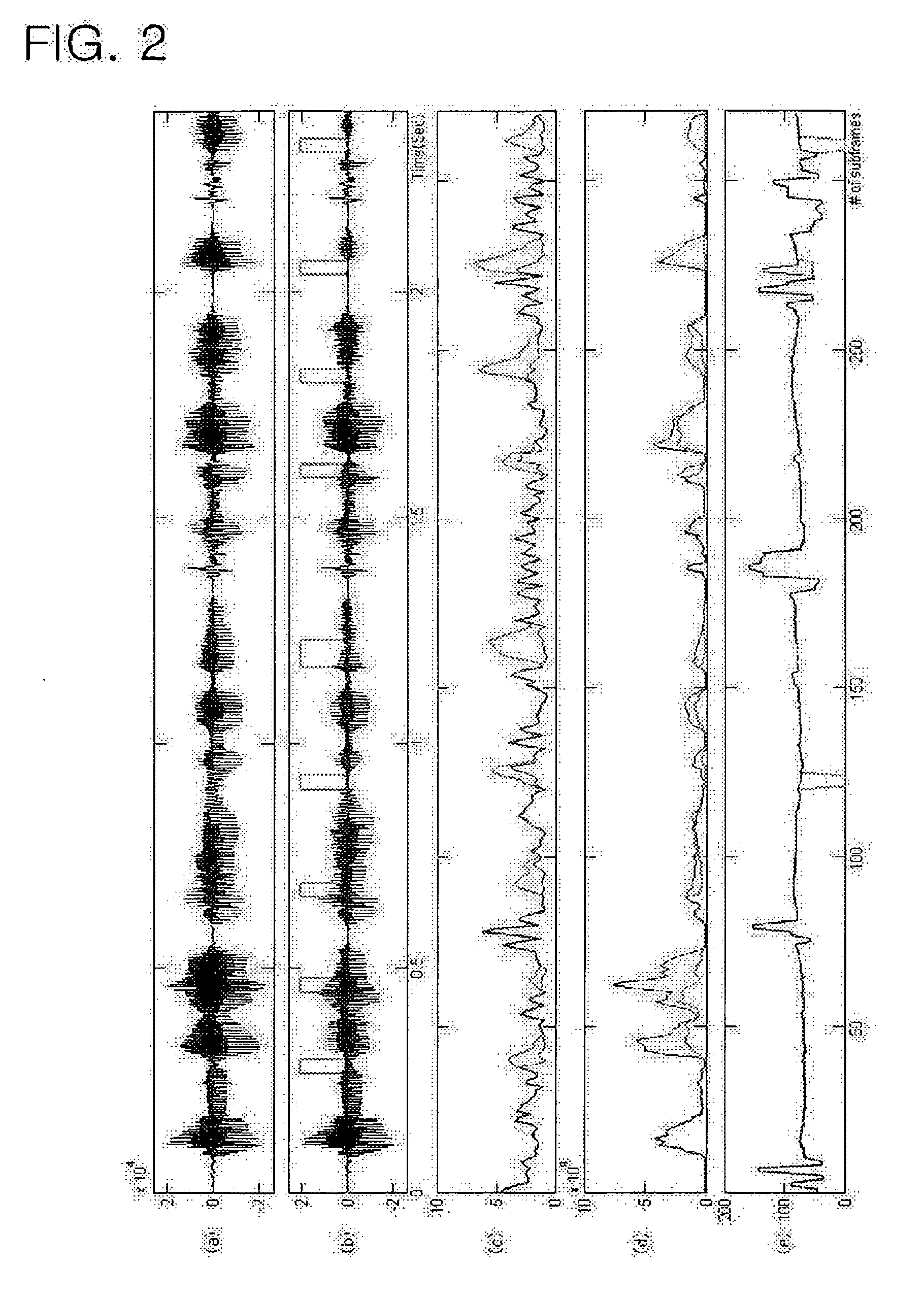
Based on the above performance analysis results illustrated in FIGS. 2A to 2E, when the single side repetition method is used in the CELP-based coder, even a slight erasure generated at the VoIP environment may deteriorate a quality of erasure recovery.
The conventional sender based erasure recovery method generally has disadvantages such as an additional delay, an increased bandwidth and a burden on computation.
On the other hand, the conventional receiver based erasure recovery method often has a limitation in recovery performance.

Method used


Image

  • Method for recovering frame erasure at voice over internet protocol (VoIP) environment
  • Method for recovering frame erasure at voice over internet protocol (VoIP) environment
  • Method for recovering frame erasure at voice over internet protocol (VoIP) environment

Examples


Embodiment Construction

[0036] Reference will now be made in detail to the preferred embodiments of the present invention, examples of which are illustrated in the accompanying drawings.

[0037] According to an exemplary embodiment of the present invention, a method for recovering a frame erasure at a voice over intemet protocol (VoIP) communications code excited linear predictive coding (CELP) environment utilizes a vector quantization (VQ) codebook index interpolation method.

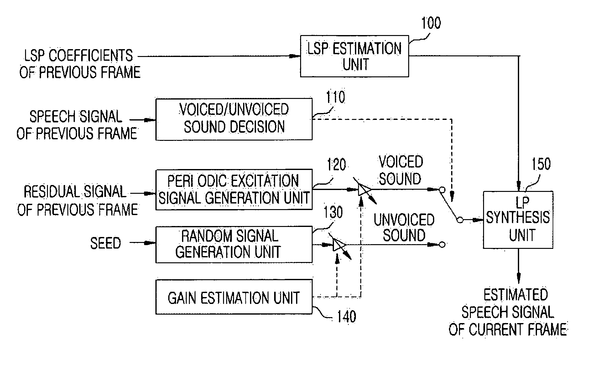
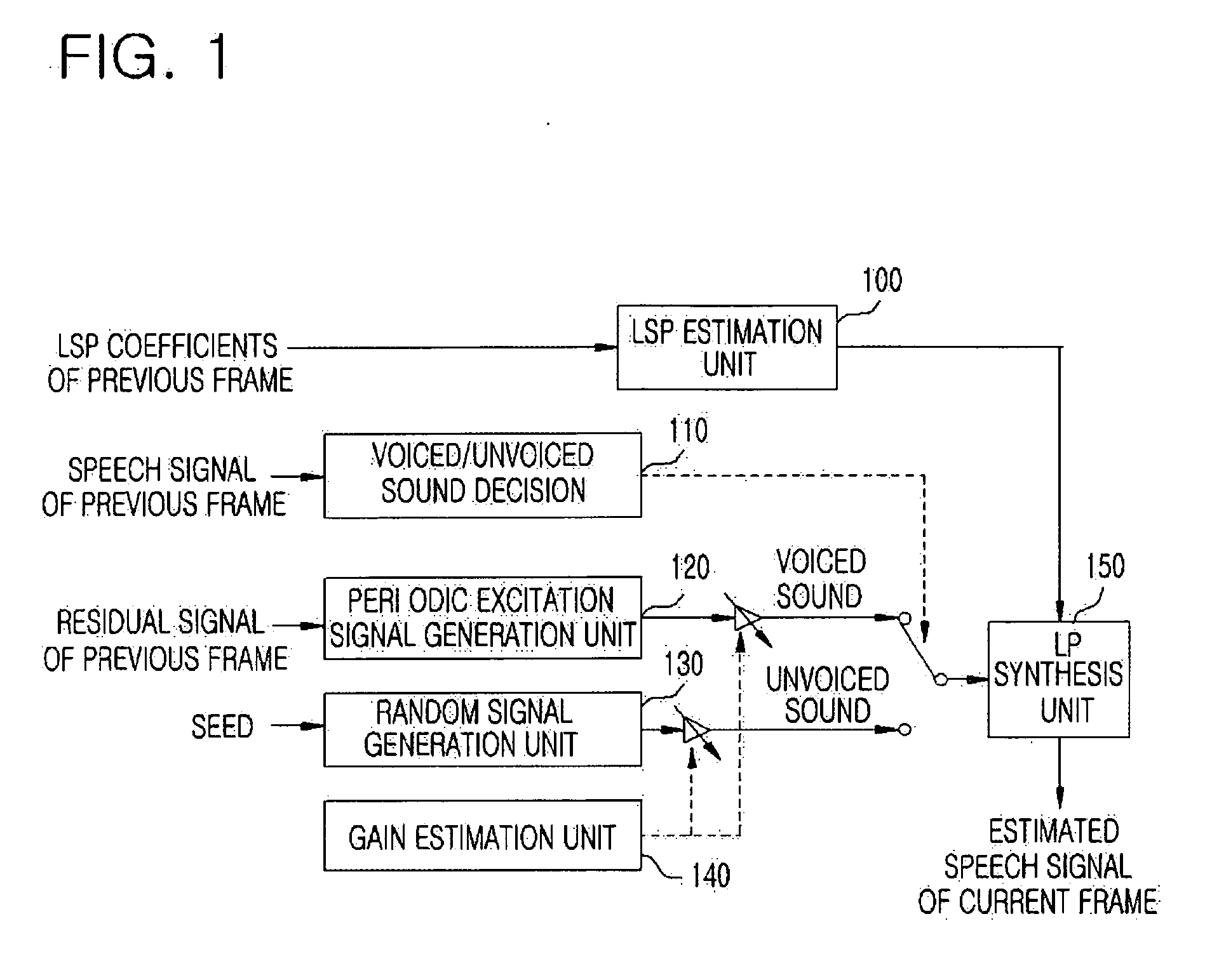
[0038] It is necessary to generate a VQ codebook index interpolation table (VCIIT) to perform the erasure recovery method. A G.723.1 coder is used as an exemplary coder for the above method. The G.723.1 coder uses VQ for gains of a line spectral pair (LSP) and an adaptive codebook. Hereinafter, the VCIIT generation will be described in detail.

[0039] The LSP VQ uses a split VQ in the form of approximately 3, approximately 3, approximately 4 sub-vectors, each including approximately 256 elements, and each vector can be expressed as th...


PUM


Abstract

A method for recovering a frame erasure at a voice over internet protocol (VoIP) environment is provided. The method includes: extracting coder parameters of received packets; if an erased packet exists during the extracting of the coder parameters, regenerating speech characteristic parameters of the erased packet by referencing a vector quantization codebook index interpolation table (VCIIT) formulated based on representative values of speech characteristic parameters reflecting auditory recognition characteristics and performing a linear interpolation on speech characteristic parameters of the normally received packets allocated previous and future of the erased packet; and recovering the erased packet by combining the regenerated speech characteristic parameters. The proposed frame erasure recovery method can minimize an additional delay and increases in bandwidth and computation and improve a capability of recovering the erasure. Also, the frame erasure recovery method can be easily implemented to a VoIP system.

Description

BACKGROUND OF THE INVENTION [0001] 1. Field of the Invention [0002] The present invention relates to a method for recovering a frame erasure at a voice over internet protocol (VoIP) environment, and more particularly, to a method for recovering a frame erasure at a VoIP environment utilizing a code excited linear predictive coding (CELP)-based coder, wherein the method can minimize a degradation of speech quality caused by an erasure of a speech frame through employing a receiver based erasure recovery method. [0003] 2. Description of the Related Art [0004] Determination of a packet erasure at a voice over internet protocol (VoIP) communications environment can vary depending on a VoIP system. Thus, a specific determination method is not described herein, and it is assumed that an implemented VoIP system determines the packet erasure and outputs the determination result. [0005] Because of several advantages such as a flexible network management of a convergence network and a reduced...

Claims


Application Information

Patent Timeline
IPC IPC(8): G10L19/12
CPCG10L19/005G10L19/00H04L1/00H04L12/66H04L2012/5603
Inventor YANG, HAE YONGLIM, JEONG SEOKLEE, KYUNG HOONYOO, SANG KYUNG
Owner ELECTRONICS & TELECOMM RES INST
Learn More