Flush toilet

Active Publication Date: 2007-03-22
TOTO LTD
View PDF1 Cites 34 Cited by
  • Summary
  • Abstract
  • Description
  • Claims
  • Application Information

AI Technical Summary

Benefits of technology

[0023] The present invention thus constituted therefore enables transfer of flushwater in the rim flushwater tank to the jet flushwater tank, as well as accurate setting of the rim flushwater tank reservoir height.
[0024] In the present invention, the jet flushwater tank and the rim fl

Problems solved by technology

H07-180202, however, the supplying of water to the jet hole and to the rim section interfere with one another due to the disposition of two drain valves on a single flushwater tank, making it difficult to appropriately apportion the amount of water supplied to the jet hole and the amount of water supplied to the rim section.
The problem is therefore presented that effective cleaning w

Method used


Image

  • Flush toilet
  • Flush toilet
  • Flush toilet

Examples


first embodiment

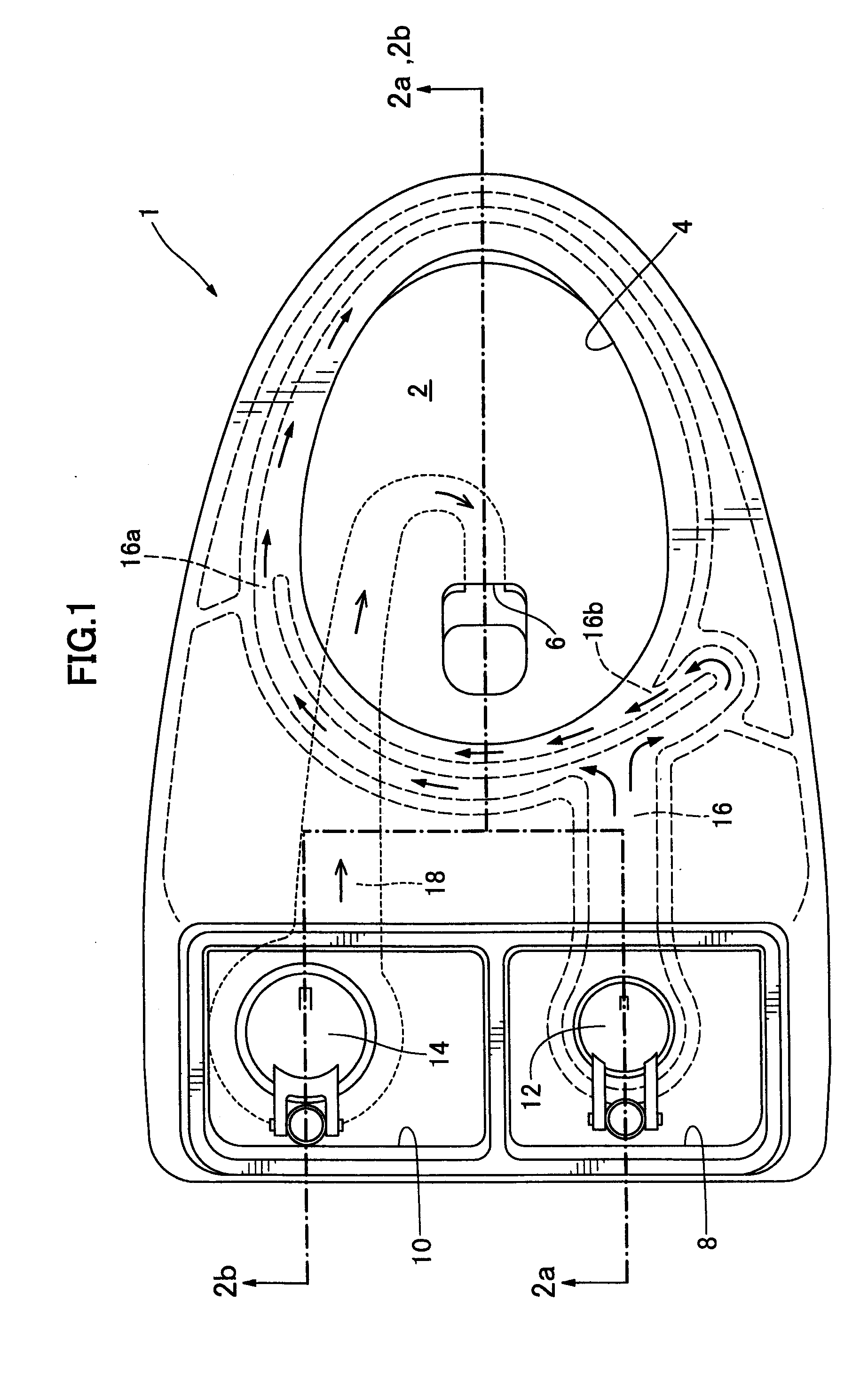
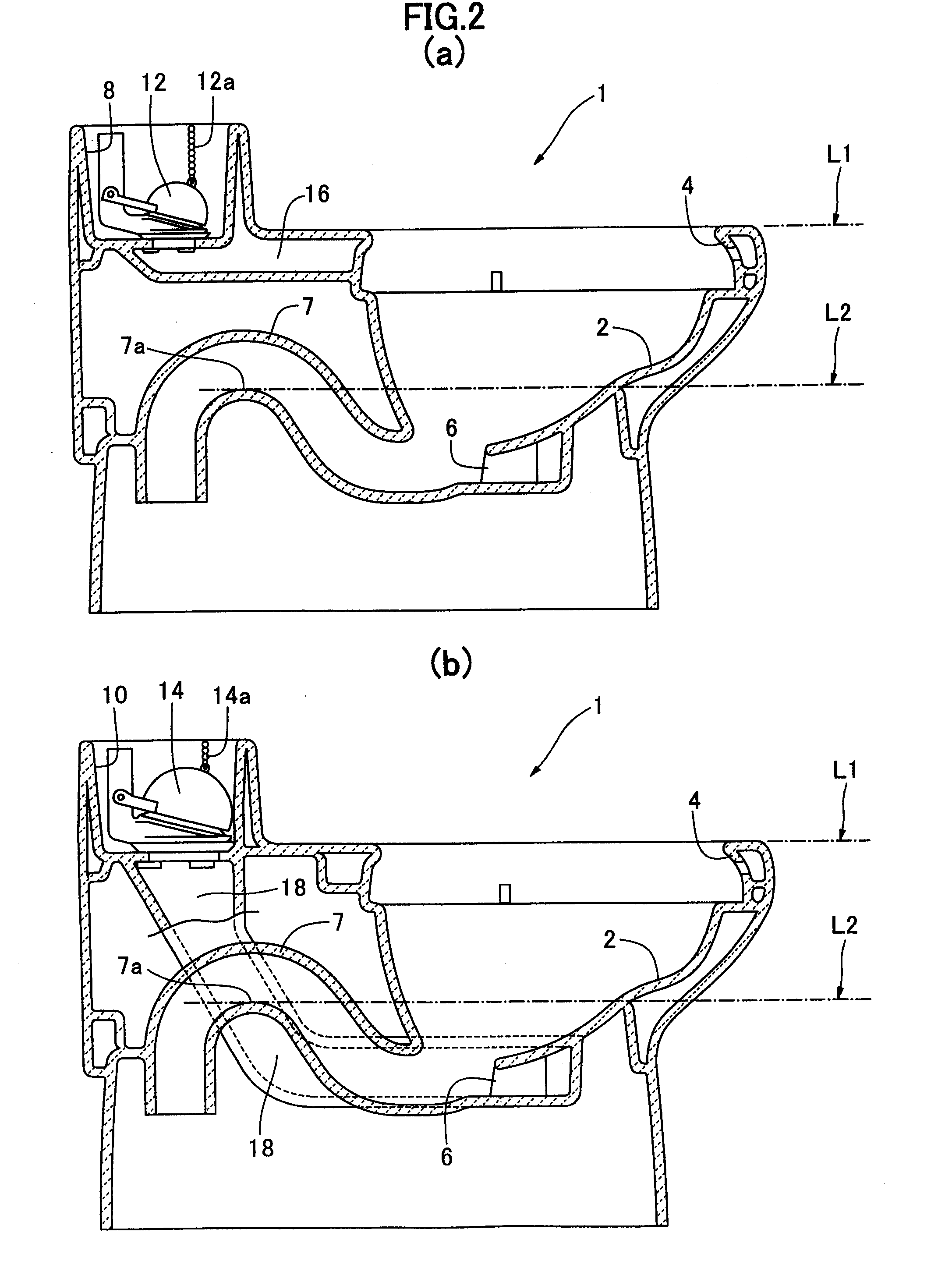
[0065] As shown in FIGS. 1 and 2, the first embodiment flush toilet of the present invention 1 comprises a bowl section 2, a rim section 4 formed at the perimeter of the top edge of the bowl section 2, a jet hole 6 formed at the bottom portion of the bowl section 2, and a trap pipe 7 communicating with the bottom portion of the bowl section 2 and connected to a drain pipe. Furthermore, the flush toilet 1 comprises a rim flushwater tank 8 which collects flushwater supplied to the rim section 4, a jet flushwater tank 10 which collects flushwater supplied to the jet hole 6, a rim drain valve 12 disposed on the rim flushwater tank 8, and a jet drain valve 14 disposed on the jet flushwater tank 10. The flush toilet 1 comprises a rim water conduit 16 which directs flushwater in the rim flushwater tank 8 to the rim section 4, and a jet water conduit 18 which directs flushwater in the jet flushwater tank 10 to the jet hole 6. In the present embodiment, the bowl section 2, the rim section 4,...

second embodiment

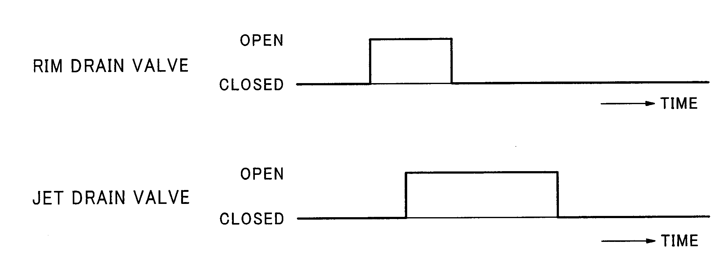
[0087] Next the operation of the second embodiment flush toilet 20 of the present invention will be explained. First, in a state in which no flushing operation is being performed, flushwater collects in the flush toilet 20 bowl section 2 up to the height L2 of the trap pipe 7 apex 7a. Also, flushwater is stored up to a predetermined water level in the rim flushwater tank 22 and the jet flushwater tank 24. Next, when the flush toilet 20 user turns the operating handle 28a to perform a flushing operation, the shaft 28b also turns. When the shaft 28b is turned the beaded chains 12a and 14a linked to the shaft 28b are respectively lifted up, causing the rim drain valve 12 and the jet drain valve 14 also to be lifted up and each of the drain valves to open. The timing at which each drain valve is opened can be freely set by the length of the beaded chains 12a and 14a and the length and angle of the crank portion formed on the shaft 28b.

[0088] The bowl section cleaning operation after th...

third embodiment

[0099] Next, the operation of the third embodiment flush toilet 30 of the present invention will be explained.

[0100] First, in a state in which no flushing operation is being performed, flushwater collects up to the height of the trap pipe 7 apex 7a in the flush toilet 30 bowl section 2. Also, flushwater is stored up to a height L3 in the rim flushwater tank 32 and up to a height L4 in the jet flushwater tank 34. Next, when a flush toilet 30 user performs a flushing operation, a drain valve operating mechanism (not shown) respectively raises the beaded chains 12a and 14a, and each drain valve is opened. The timing at which each drain valve is opened can be freely set by the length of the beaded chains 12a and 14a and the drain valve operating mechanism.

[0101] The bowl section cleaning operation after the rim drain valve 12 and the jet drain valve 14 are opened is similar to the first embodiment; an explanation thereof is therefore omitted.

[0102] Next, the supply of water to each o...


PUM


Abstract

Providing a flush toilet wherein the amount of water supplied to the jet hole and the amount of water supplied to the rim section are independently controlled. The present invention is a flush toilet (1) for supplying flushwater from a flushwater tank, the flush toilet comprising a bowl section (2) at the bottom portion of which is formed a jet hole; a jet flushwater tank (10) for storing flushwater to be supplied from the jet hole; a jet drain valve (14) disposed on the jet flushwater tank; a jet water conduit (18) for conducting flushwater which has passed through the jet drain valve to the jet hole; a rim section (4) disposed on the upper portion of the bowl section; a rim flushwater tank (8) for storing flushwater supplied to the rim section; a rim drain valve (12) disposed on the rim flushwater tank; and a rim water conduit (16) for conducting flushwater passed through the rim drain valve to the rim section.

Description

CROSS-REFERENCE TO RELATED APPLICATIONS [0001] This is a continuation of PCT International application no. PCT / JP2005 / 001343, with an international filing date of Jan. 31, 2005, which is incorporated by reference herein, which claims priority to JP 2004-063823, filed Mar. 8, 2004.TECHNICAL FIELD [0002] The present invention relates to a flush toilet, and more particularly to a flush toilet which supplies flushwater from a flushwater tank. BACKGROUND ART [0003] Tank-type flush toilets, in which flushwater supplied from a water main is collected in a flushwater tank, and a bowl section is cleaned by flushing with the flushwater in the tank, are widely used. In flush toilets of this type, in which the bowl section is cleaned by causing flushwater to be expelled from a rim section in the upper part of the bowl section and a jet hole, flushwater in the flushwater tank is divided and supplied to the rim section and to the jet hole. That is, when a drain valve disposed on the bottom portio...

Claims


Application Information

Patent Timeline
IPC IPC(8): E03D11/18E03D11/02E03D1/26E03D11/08
CPCE03D2201/30E03D11/08E03D1/24E03D1/26E03D11/02
Inventor ASADA, KYOJIYONEDA, TOSHIFUMIHIRAKAWA, TOMOHIRO
Owner TOTO LTD
Why Eureka
Try Eureka