
Apparatus and method for cutting sewn material in sewing machine

a sewing machine and elongated technology, applied in the field of sewing machines, can solve the problems of increasing the cost of sewing machines, increasing the cost and size of sewing machines, and increasing the cost and siz

Inactive Publication Date: 2007-03-22
TOKAI IND SEWING MACH CO LTD
View PDF11 Cites 13 Cited by
  • Summary
  • Abstract
  • Description
  • Claims
  • Application Information

AI Technical Summary

Benefits of technology

[0007] It is an object of the present invention to provide a cutting apparatus which can be caused to move from a retracted position to a cutting position and caused to hook a string material (elongated sewn material) by a single drive source.
[0009] It is still another object of the present invention to provide a cutting apparatus and method which can pull a greater amount of string material (elongated sewn material) out of a guide unit after the string material is cut, as compared with the conventional art.
[0011] With this arrangement, the same drive device can drive the main body to move from the retracted position to the cutting position and cause the sewn material to be hooked on the hook section. Thus, the cutting apparatus has to be provided with only one drive source, and therefore, the cutting apparatus can be reduced in cost and size.
[0014] With this arrangement, the single drive source can drive the main body to move from the retracted position to the cutting position, cause the sewn material to be hooked on the hook section, and drive the cutting blade to move in response to driving operation of the drive device. Thus, the cutting apparatus can be further reduced in cost and size.
[0016] By thus moving the object of sewing (fabric) with the sewn material sewn thereon to the position which is the predetermined distance away from the sewing position of the sewing needle, an excess amount of the sewn material can be pulled out of the guide unit. It is therefore possible to pull a sufficient amount of the sewn material out of the guide unit even after the sewing material is cut.

Problems solved by technology

However, there has been the problem that, since such a cutting apparatus driven by a plurality of drive sources is expensive and large in size, the sewing machine is also expensive and making the sewing machine compact is difficult.
There have also been known cutting apparatuses of a type which is provided with the third drive source for driving a cutting blade which actually cuts a string material, but the cutting apparatuses of this type would suffer from the inconveniences that the cost and size are further increased.
Particularly in multi-head sewing machines of a type which is provided with a plurality of machine heads, the string material and the upper thread must be pulled out in each machine head, which is very troublesome.

Method used


Image

  • Apparatus and method for cutting sewn material in sewing machine
  • Apparatus and method for cutting sewn material in sewing machine
  • Apparatus and method for cutting sewn material in sewing machine

Examples


Embodiment Construction

[0034] The present invention will now be described in detail with reference to the drawings showing a preferred embodiment thereof.

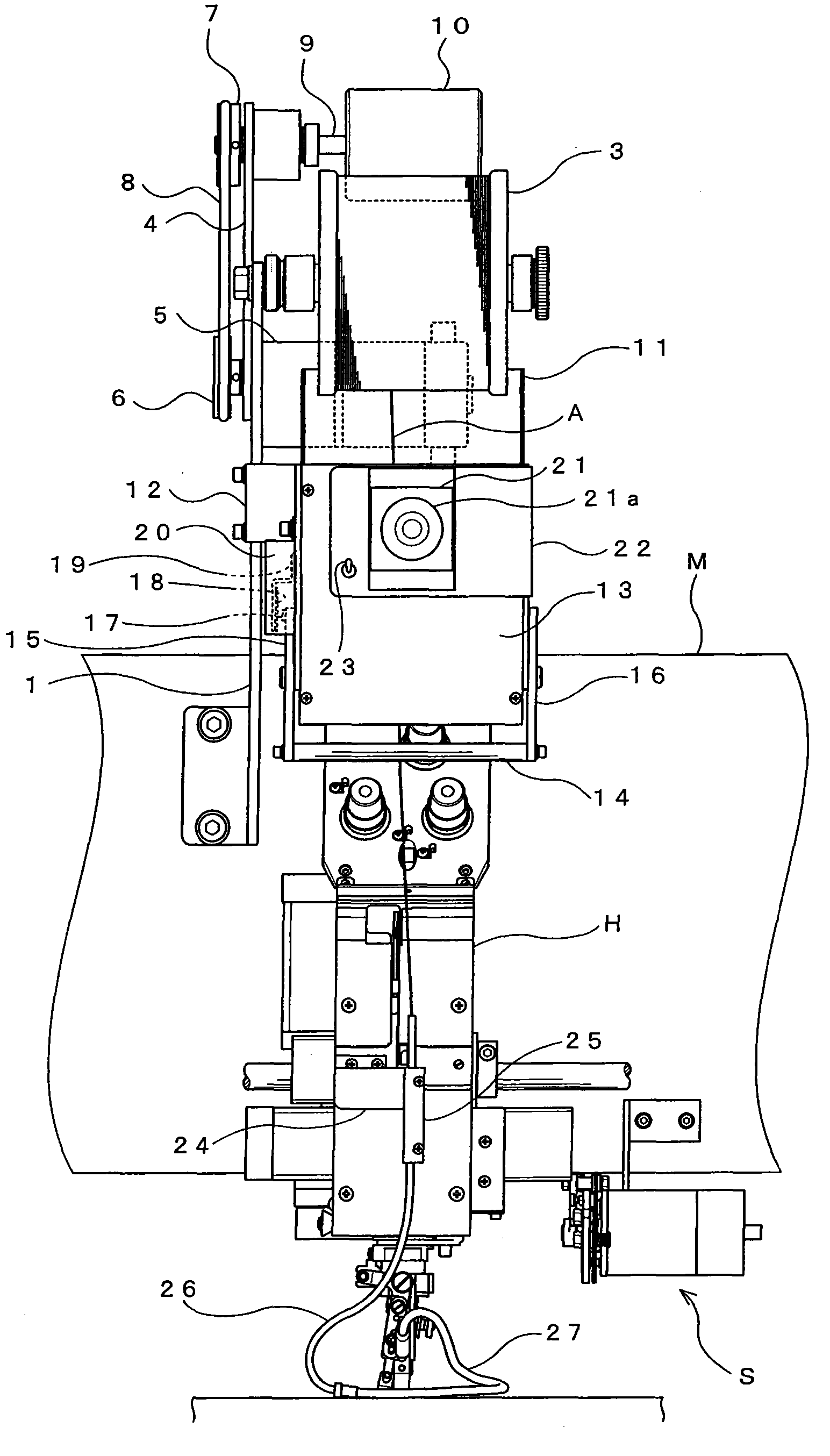
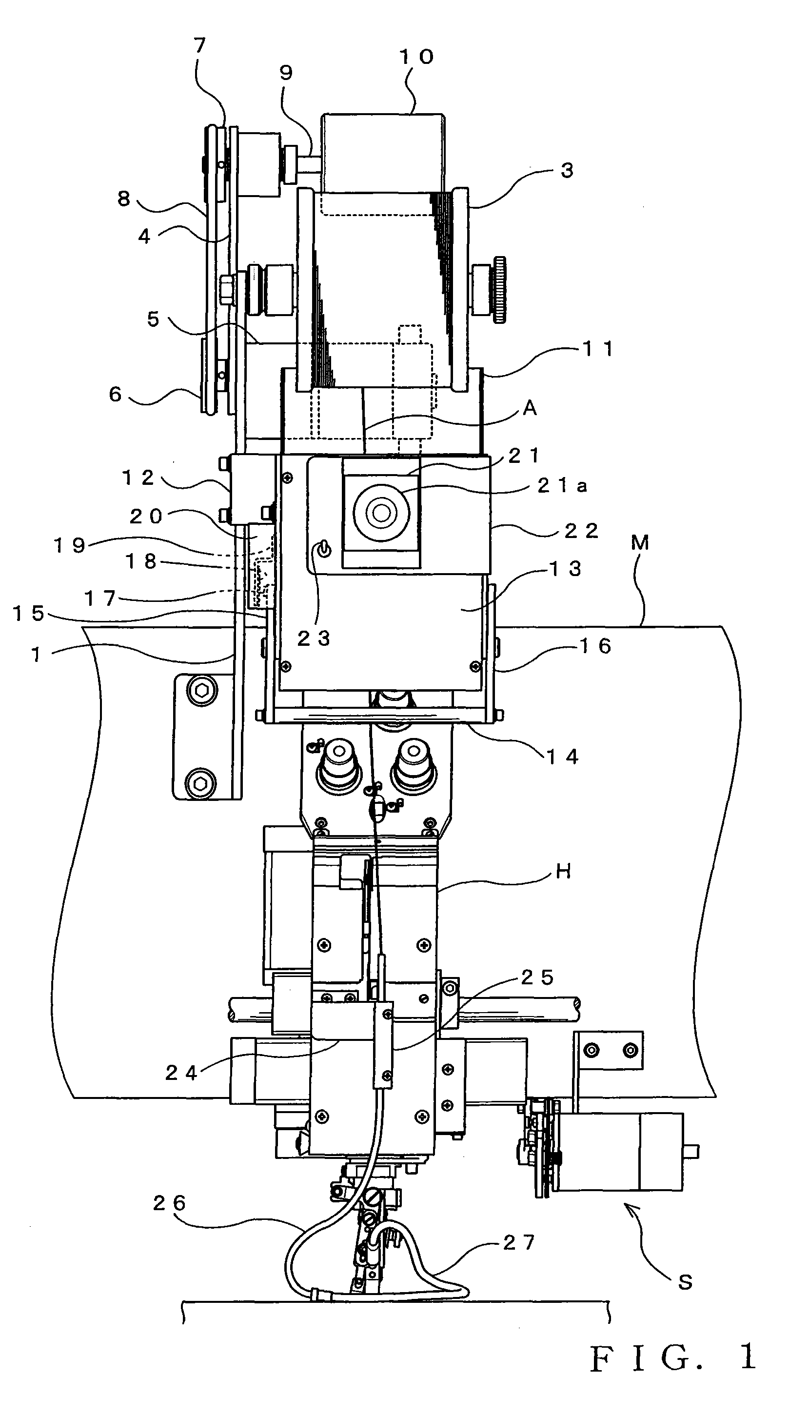
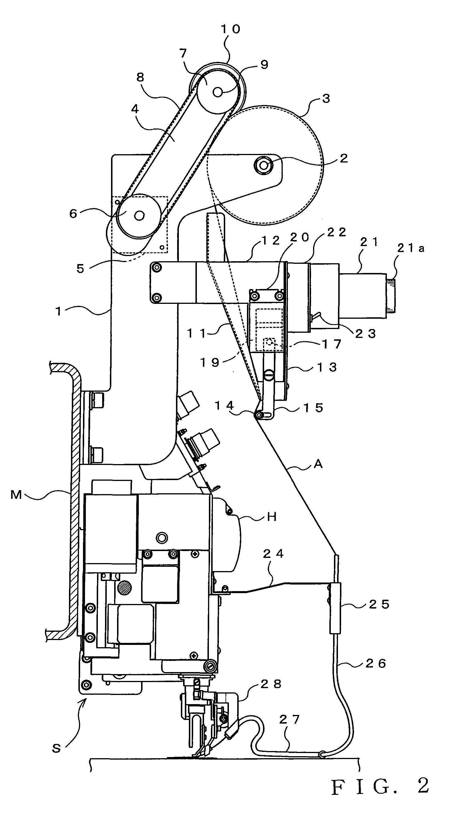
[0035]FIG. 1 is a front view showing an external appearance of part of an embroidering sewing machine in accordance with an embodiment of the present invention. FIG. 2 is a left side view of the embroidering sewing machine taken from a left side of the machine shown in FIG. 1. Construction of the embroidering sewing machine will be described below with primary reference to FIGS. 1 to 2. Whereas a plurality of machine heads H are disposed at predetermined intervals on a front surface (i.e., a surface closer to a reader of FIG. 1 and a right side surface in FIG. 2) of a machine frame M of the actual embroidering sewing machine, only one of the machine heads H is shown in the figures to facilitate understanding of the following description.

[0036] In addition to such machine heads H, a support member 1 is fixed, via bolts or the like, to a predetermined po...


PUM


Abstract

A cutting apparatus which is comprised of a main body including a hook section for hooking thereon a sewn material, a fixed blade fixed to a predetermined position of the main body, a cutting blade that cuts the sewn material by moving toward the fixed blade, and a drive device that moves the main body between a predetermined retracted position that does not interferer with sewing operation and a predetermined cutting position for cutting the sewn material. In sewing the sewn material, the main body is held at the retracted position, and in cutting the sewn material, the main body is caused to move from the retracted position to the cutting position by the drive device. The hook section is provided in the main body and at such a position as to hook thereon the sewn material as the main body moves to the cutting position. In cutting the sewn material, the cutting blade moves toward the fixed blade in response to driving operation of the drive device. The cutting apparatus is disposed a predetermined distance away from the sewing position.

Description

BACKGROUND OF THE INVENTION [0001] 1. Field of the Invention [0002] The present invention generally relates to sewing machines of a type which sews an elongated sewn material, such as a tape or cord, to an object of sewing (typically, fabric) through lock stitching. More particularly, the present invention relates to an apparatus and method for cutting an elongated sewn material, for example, at the end of sewing. [0003] 2. Description of the Related Art [0004] Conventionally, there have been known sewing machines of a type which includes a vertically driven needle bar, a sewing needle fixed to a lower end portion of the needle bar, a rotary member mounted concentrically with the needle bar and freely rotatable about the axis, and a guide fixed to the rotary member, for guiding an elongated sewn material (e.g., string-shaped embroidering member, such as a tape or cord) to a sewing position of the sewing needle. The sewing machines of the type operate to sew the string material to a ...

Claims


Application Information

Patent Timeline
IPC IPC(8): D05B3/00
CPCD05C7/08D05B37/04D05B27/10D05B35/06D05B37/00
Inventor KONDO, TETSUROU
Owner TOKAI IND SEWING MACH CO LTD
Learn More