
Elevator installation with drivebelt pulley and flat-beltlike suspension means

a technology of drive belt and suspension means, which is applied in the direction of elevators, building lifts, transportation and packaging, etc., can solve the problems of excessively high tractive capacity between the drive belt traction sheave and the application of such a drive belt pulley, and achieve the effect of functional and safety problems

Inactive Publication Date: 2007-03-22
INVENTIO AG
View PDF19 Cites 47 Cited by
  • Summary
  • Abstract
  • Description
  • Claims
  • Application Information

AI Technical Summary

Benefits of technology

This new design allows for better utilizing space within buildings without adding extra weight or making it difficult to move around safely due to high tension caused when lifting heavy loads over uneven surfaces such as rocks.

Problems solved by technology

The technical problem addressed in this patent is the excessive tractive capacity and high friction between the drivebelt pulley and the flat-beltlike suspension means in elevator installations, which can lead to functional and safety problems and prevent load equalization between the suspension means. Additionally, the absence of guide grooves and guide ribs in the drive arrangement can result in a failure of lateral guidance of the flat belt on the belt sheave.

Method used


Image

  • Elevator installation with drivebelt pulley and flat-beltlike suspension means
  • Elevator installation with drivebelt pulley and flat-beltlike suspension means

Examples


Embodiment Construction

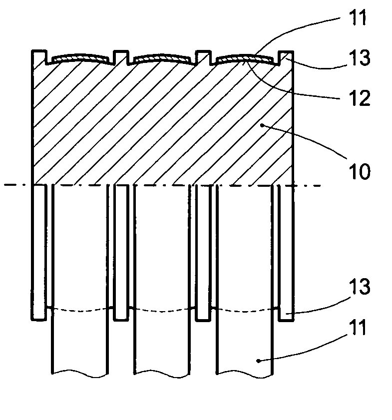
[0038] Shown in FIG. 1 is a drivebelt sheave 10 with several flat-beltlike suspension means or members 11. The running surfaces 12 of the drivebelt sheave 10 are slightly arched perpendicular to the circumferential direction, as a result of which a certain self-centering of the suspension means 11 in the middle of the respective running surface 12 is attainable. The centering effect depends inter alia on the magnitude of the coefficient of friction between the suspension means 11 and the running surfaces 12 of the drivebelt sheave 10, i.e. a high coefficient of friction hinders an optimal centering effect of the running-surface arching. To obtain best possible self-centering of the suspension means 11 on the drivebelt sheave 10, but also to prevent the aforesaid dangerous raising of the elevator car with blocked counterweight, and to ensure load equalization between the suspension means 11, the running surfaces 12 are friction-reducing coated or friction-reducing surface treated. Di...


PUM


Abstract

An elevator installation with a drivebelt sheave and a flat-beltlike suspension member that bears the elevator car and the counterweight, and that is driven by the drivebelt sheave. A running surface or a partial running surface of the drivebelt sheave, via which the flat-beltlike suspension member rests on the drivebelt sheave, is friction-reducingly coated or friction-reducingly surface treated.

Description


Claims


Application Information

Patent Timeline
Owner INVENTIO AG
Features
  • Generate Ideas
  • Intellectual Property
  • Life Sciences
  • Materials
  • Tech Scout
  • Unparalleled Data Quality
  • Higher Quality Content
  • 60% Fewer Hallucinations
Learn More