

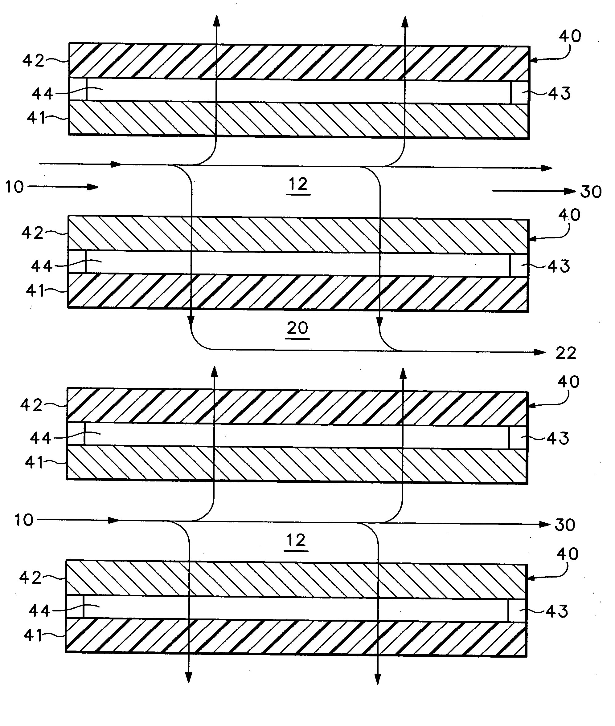
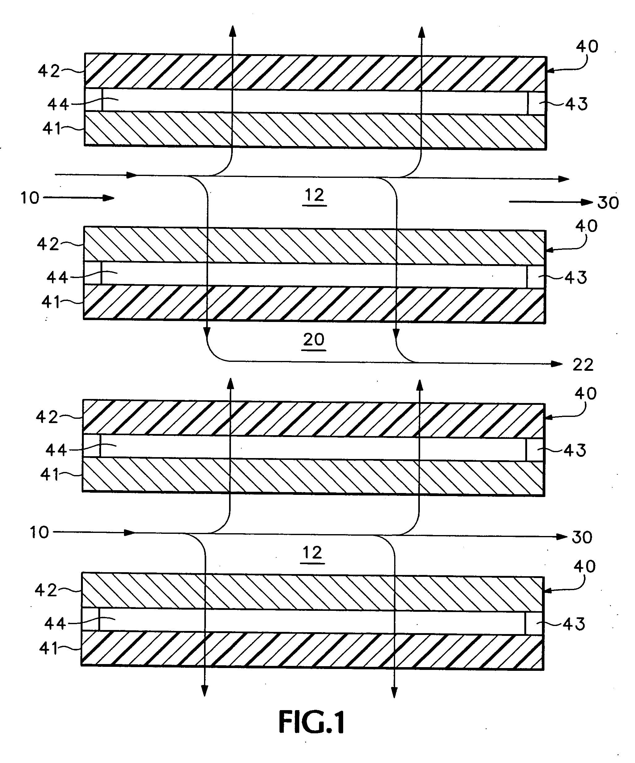
Cross-flow filter cassette
a filter cassette and cross-flow technology, applied in the direction of membranes, instruments, separation processes, etc., can solve the problems of affecting the filtering capacity, the yield of targeted substances, and the service life of the cross-flow filtration uni
- Summary
- Abstract
- Description
- Claims
- Application Information
AI Technical Summary
Problems solved by technology
Method used
Image

Examples
example 1
[0023] A cross-flow filtration cassette having a feed inlet and feed flow channel; a permeate flow channel and a permeate outlet; a retentate outlet; and 24 cellulose acetate two-ply microporous separation membranes was constructed wherein each two-ply membrane had a front side ply that faced the feed channel and a back side ply that faced the permeate channel. Each of said plies physically laid one on top of another and were joined at their peripheries by spacers, but not bonded together in the area between the spacers. The flow of liquid feed through the separation membranes was a cross-flow mode, i.e., tangential over the surface of each membrane and the flow of permeate through the membrane was from the front side ply to the back side ply, with recycle of the retentate. The filtration cassette was used to filter 127 mL of a yeast cell suspension (pichia) with a cell concentration of 6×10⁶ yeast cells (retentate content) per mL, which contains a targeted protein having a molecula...
example 2
[0027] A cross-flow filtration cassette of substantially the same design as the one in Example 1 was constructed with 20 two-ply membranes wherein the average pore size of the front side ply of each membrane was 0.65 μm while the average pore size of the back side ply for each membrane was 0.45 μm, so that the average pore size of the front side ply was 1.4 times the average pore size of the back side ply.
[0028] 130 mL of a yeast cell suspension having a cell concentration of 107 yeast cells (retentate content) per mL containing BSA as the target protein (having a molecular weight of 66,000 Daltons (permeate content) was filtered through the cross-flow filtration cassette. Filtration took place in a cross-flow mode with recycle of the retentate. The transmembrane pressure was constant at 0.55 bar, while the pressure at the feed inlet was 0.9 bar, with 0.4 bar at the retentate outlet and 0.1 bar at the permeate outlet. 70 L of the cell suspension was concentrated to a final volume o...
example 3
[0031] A cross-flow filtration unit fabricated in the form of a filter cassette was employed with two-ply membranes exposed to the liquid feed and having a total membrane surface area of 0.4 m2, and which had 13 feed flow channels and 12 permeate flow channels. The membrane layers facing the feed flow channels were of cellulose acetate, having an average pore size of 0.8 μm and the membrane layers facing the permeate flow channels were also from cellulose acetate, but having an average pore size of 0.2 μm, so that the ratio of pore sizes was 4.
[0032] Cross-flow filtration was carried out with the same amount of the same pichia yeast cell suspension of Example 1. The filtration took place in a cross-flow mode with recycle of the retentate and with the same pressure parameters as in Example 1.
[0033] A volume of 7.3 L of the cell suspension was concentrated to a final volume of 1 L. The average permeate flow rate was 0.810 L / min·m2. Filtration was conducted for 19 minutes. The concen...
PUM
| Property | Measurement | Unit |
|---|---|---|
| molecular weight | aaaaa | aaaaa |
| pore size | aaaaa | aaaaa |
| pore size | aaaaa | aaaaa |
Abstract
Description
Claims
Application Information