Crossflow filtration system with quick dry change elements

a filtration system and cross-flow technology, applied in the direction of filtration separation, multi-stage water/sewage treatment, separation process, etc., can solve the problem of only being required for a certain time, and achieve the effect of convenient connection, quick and easy replacement, and adjustment of filtering characteristics of the cross-flow filtration system

Inactive Publication Date: 2005-08-11
3M INNOVATIVE PROPERTIES CO
View PDF57 Cites 28 Cited by
  • Summary
  • Abstract
  • Description
  • Claims
  • Application Information

AI Technical Summary

Benefits of technology

[0007] When the filtering capacity of the crossflow filtration media element is consumed, the unitary construction of the cartridge allows for quick and easy replacement with a new cartridge containing a new crossflow filtration media element. As there is no disassembly of the cartridge filter, the replacement process can be accomplished without water spillage. In addition, the time required is only that necessary to rotatably remove a spent cartridge and rotatably install a new cartridge. Generally, disassembly and reassembly of the housing and filter cartridge can be performed by hand without any tool, although a tool can be used if desired. In certain embodiments, the filtering characteristics of the crossflow filtration system can be adjustably varied by replacing a cartridge filter having a first media with a new cartridge filter having a second type of filtration media. In addition, operational performance of the crossflow filtration system can be adjusted, which may be desired due to changes in the feedwater chemistry, simply by replacing cartridge filters wherein the cartridge filter includes a specific orifice, thereby controlling overall recovery of the crossflow filtration system. Adjustment can be performed by varying the backpressure on the concentrate stream, for example, by using a flow restrictor such as an orifice or valve.
[0010] In another aspect, the disclosure pertains to a crossflow filtration manifold comprising a manifold body and a manifold connection. The manifold body and the manifold connection can define a feed flow channel, a permeate flow channel and a concentrate flow channel. The manifold connection can include an engagement member for allowing rotatable connection with a cartridge filter. The crossflow filtration manifold can include a flow restriction, such as a valve or orifice, in the concentrate flow channel to backpressure and control the water recovery for a crossflow filtration cartridge. The crossflow filtration manifold can include a biased closed valve in the feed flow channel to prevent water spillage when the manifold is not engaged with a cartridge filter. The crossflow filtration manifold can include a check valve in the permeate flow channel to prevent backward flow of filtered water through the manifold.
[0013] In another aspect, the disclosure pertains to a pressure damping assembly for use in damping pressure fluctuations within a water treatment system. The pressure damping assembly can be fluidly connected between a storage tank and a shut-off valve so as to reduce or eliminate the effect of pressure fluctuations when filtered water is drawn from the storage tank. By reducing or eliminating pressure fluctuations before they reach the shut-off valve, undesirable chattering of the shut-off between system open and system closed configurations can be eliminated. In some presently preferred representative embodiments, the pressure damping assembly can comprises a stand-alone assembly for fluidly mounting between the storage tank and the shut-off valve. In some alternative presently preferred representative embodiments, the pressure damping assembly can integral to the shut-off valve or to a manifold assembly in which the shut-off valve is operably attached. In some presently preferred representative embodiments, the pressure damping assembly can comprise a series of ribs and openings within a fluid conduit defining a winding path in which pressure fluctuations are dampened prior to effecting the shut-off valve.

Problems solved by technology

In addition, the time required is only that necessary to rotatably remove a spent cartridge and rotatably install a new cartridge.

Method used


Image

  • Crossflow filtration system with quick dry change elements
  • Crossflow filtration system with quick dry change elements
  • Crossflow filtration system with quick dry change elements

Examples


Embodiment Construction

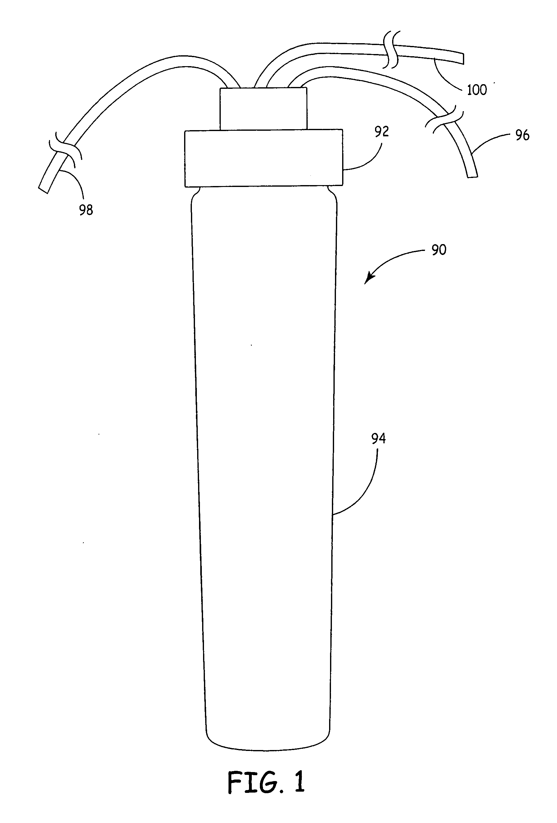
[0041] As illustrated in FIG. 1, an embodiment of a crossflow filtration assembly 90 of the present disclosure comprises a manifold assembly 92 and at least one crossflow cartridge filter 94. As depicted in FIG. 1, an embodiment of the crossflow filtration assembly 90 includes a supply tube 96, a concentrate tube 98 and a permeate tube 100.

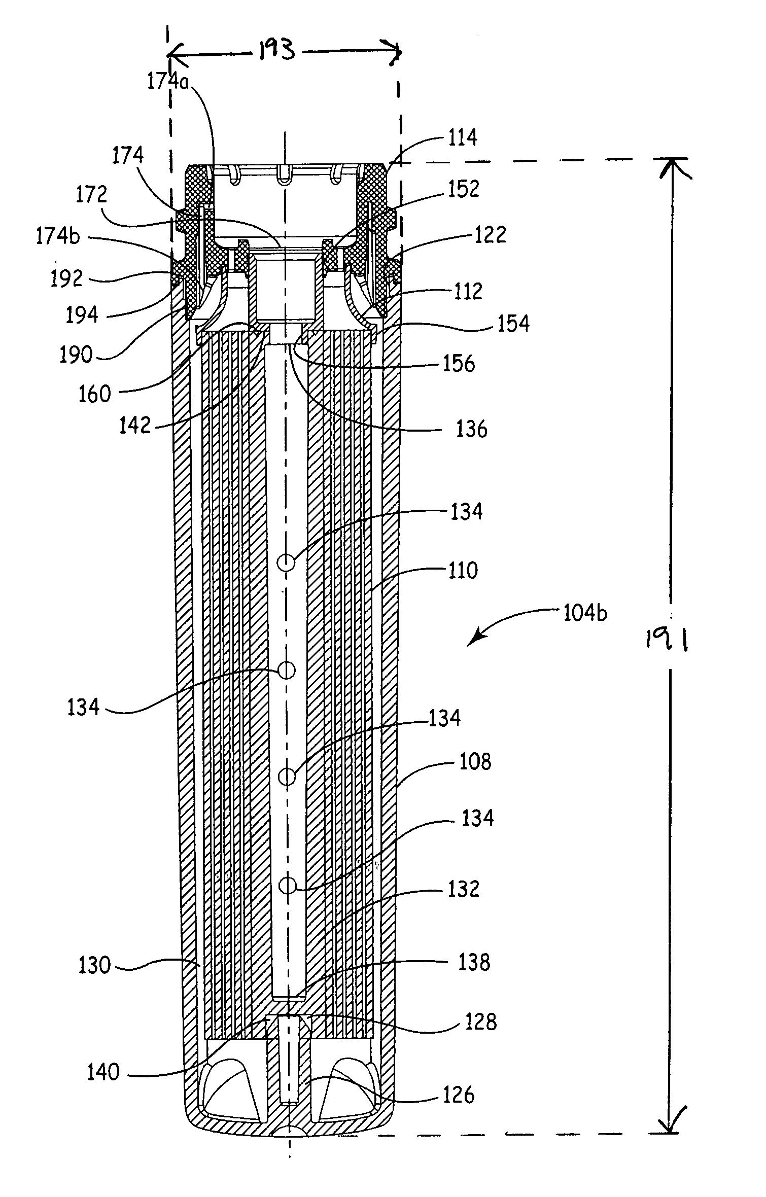
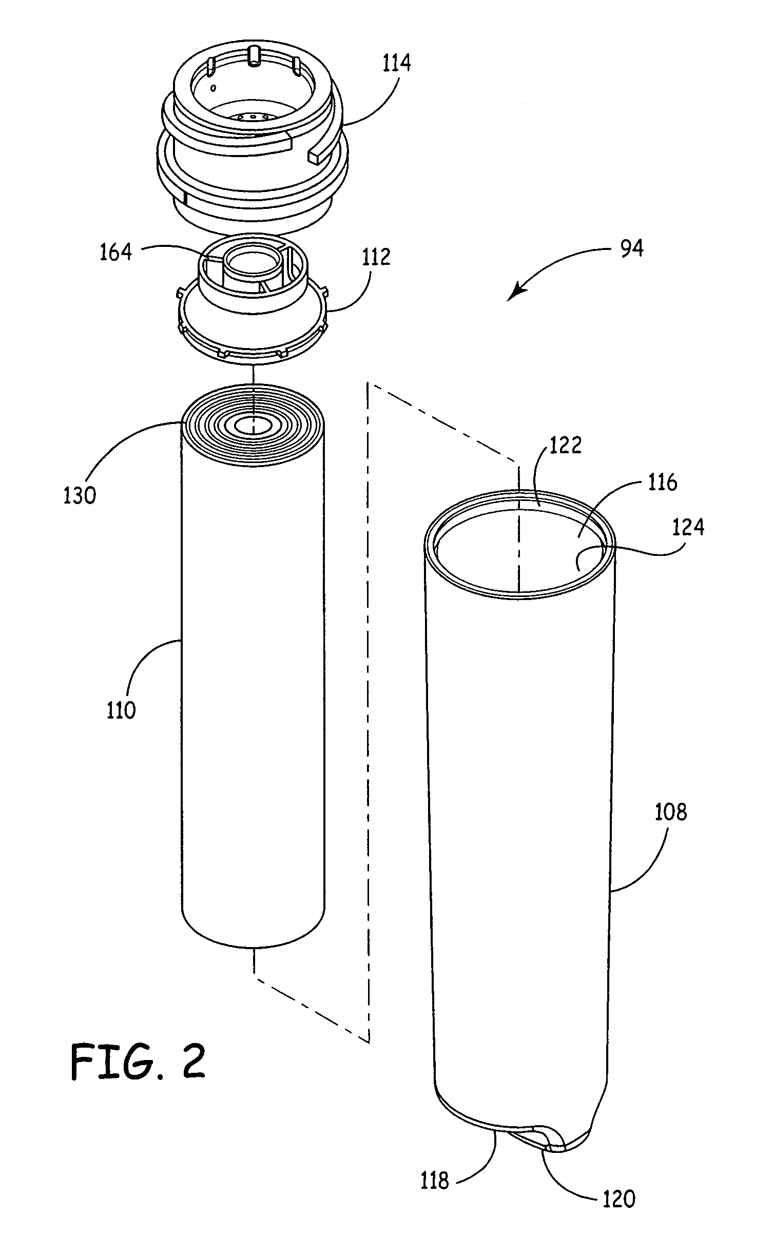
[0042] The crossflow cartridge filter 94 is more clearly illustrated in FIG. 2. Generally, crossflow cartridge filter 94 comprises a filter housing 108, a crossflow filtration element 110, a flow director 112 and a filter cap 114. Filter housing 108, flow director 112 and filter cap 114 are constructed of suitable polymers for example, polypropylene or polyethylene. Crossflow cartridge filter 94 is constructed so as to be fixedly sealed and closed such that when replacement is necessary, the entire cartridge is replaced as opposed to replacing individual cartridge components such as crossflow filtration element 110. This system has a single filte...


PUM

PropertyMeasurementUnit
lengthaaaaaaaaaa
outer diameteraaaaaaaaaa
pressureaaaaaaaaaa

Abstract

A crossflow filtration system including at least one quick dry change crossflow filtration cartridge designed to rotatably interface with a manifold assembly. The quick dry change crossflow filtration cartridge can comprise a membrane element, for example an ultrafiltration membrane, microfiltration membrane, nanofiltration membrane or high-flux reverse osmosis membrane element enclosed within a housing. The quick dry change cartridge includes an inlet stream, a permeate stream and a concentrate stream. The manifold assembly includes three similar flow paths; an inlet stream, a permeate stream and a concentrate stream. When engaged, the cartridge and manifold assembly define continuous inlet flow paths, permeate flow paths and concentrate flow paths that connect across the interface. Thus, all of the connections to the water filtration system can be made onto the manifold, and the resulting connected system is compact and easy to connect.

Description

[0001] The present application is a Continuation-In-Part application of U.S. patent application Ser. No. 10 / 838,140, filed May 3, 2004 and entitled “CROSSFLOW FILTRATION SYSTEM WITH QUICK DRY CHANGE ELEMENTS“, which claims the benefit of U.S. Provisional Application No. 60 / 467,663, filed May 2, 2003 and entitled “RESIDENTIAL REVERSE OSMOSIS SYSTEM WITH QUICK DRY CHANGE ELEMENTS,” both of which are herein incorporated by reference to the extent not inconsistent with the present disclosure.BACKGROUND OF THE DISCLOSURE [0002] The present disclosure relates generally to the field of water filtrations systems. More specifically, the present disclosure relates to crossflow filtration systems utilizing a crossflow filtration element, which in some representative embodiments are capable of being added and replaced by a quick connect attachment. Furthermore, in some representative embodiments, the crossflow filtration systems are capable of enhanced filtration capacity with the use of a stor...

Claims


Application Information

Patent Timeline
Patent Type & Authority Applications(United States)
IPC IPC(8): B01D61/00B01D61/08B01D61/10B01D61/18B01D61/20B01D63/06B01D63/10B01D65/00
CPCB01D35/153B01D61/08C02F2201/006B01D61/10B01D61/18B01D61/20B01D63/10B01D65/00B01D2201/302B01D2201/4015C02F1/441C02F1/442C02F1/444B01D35/306B01D61/081
Inventor FRITZE, KARLMARKS, NATHAN E.
Owner 3M INNOVATIVE PROPERTIES CO
Why Eureka
Try Eureka