Protection circuit for permanent magnet synchronous motor in filed weakening operation

a technology of protection circuit and synchronous motor, which is applied in the direction of process and machine control, multiple dynamo-motor starters, emergency power supply arrangements, etc., can solve the problems of pmsm showing two potentially dangerous conditions, bodily injury, and no provision is made to return this energy back to the power line, etc., and achieves the effect of shortening the motor terminal

Active Publication Date: 2007-03-22
INFINEON TECH AMERICAS CORP
View PDF17 Cites 52 Cited by
  • Summary
  • Abstract
  • Description
  • Claims
  • Application Information

AI Technical Summary

Benefits of technology

This invention relates to a safety circuit designed to prevent failure in an inverter circuit used to drive a permanent magnet synchronous motor (PMSM). A primary source of energy supplies power to the circuit through a series of switches controlled by a gate driver circuit. However, if this primary source fails, there is a backup system ready to take over and ensure safe operation of the motor. Specifically, the backup system ensures that all necessary components are still operational even if other parts have failed. Turning on certain switches can quickly stop or slow down the movement of the motor, which prevents damage from occurring due to uncontrolled electrical arcs or excessive heat.

Problems solved by technology

The technical problem addressed in this patent is how to protect against potential danger caused by a sudden increase in voltage and current in a DC-ac inverter motor controller driving a PMSM motor, should there be a failure in the controller or other parts of the system. Such a scenario would require quick response measures to avoid damage to the system components and ensure safe operation of the motor.

Method used


Image

  • Protection circuit for permanent magnet synchronous motor in filed weakening operation
  • Protection circuit for permanent magnet synchronous motor in filed weakening operation
  • Protection circuit for permanent magnet synchronous motor in filed weakening operation

Examples


Embodiment Construction

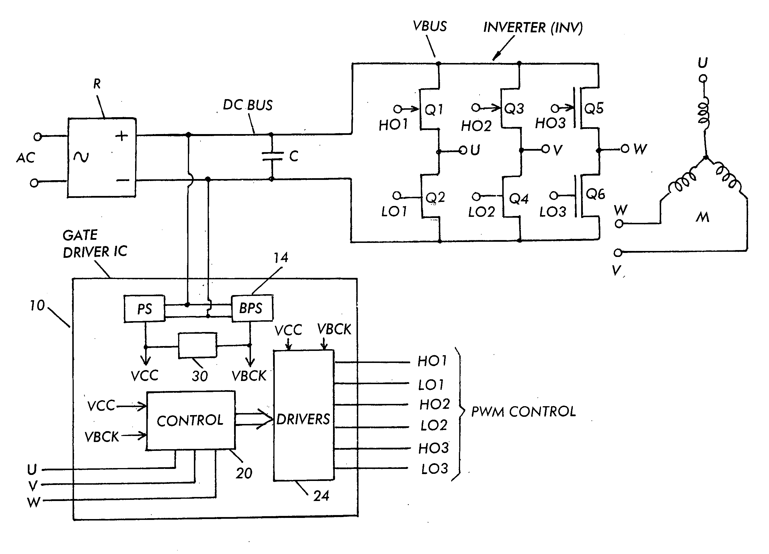
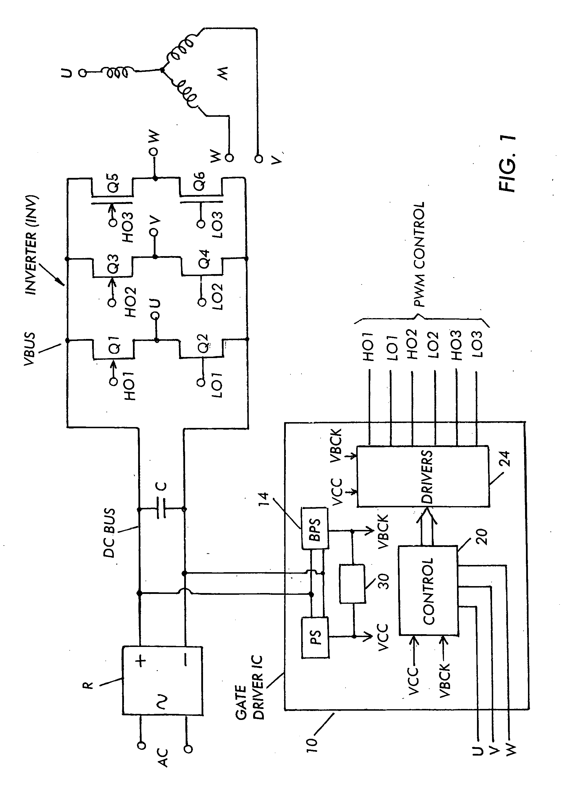
[0017]FIG. 1 shows a block diagram of a PMSM controller. Alternating current (AC) from the main supply is fed to a rectifier stage R which can include, for example, a boost converter stage. The output of the rectifier R is a DC bus voltage. The DC bus voltage is smoothed by a bulk storage capacitor C. The DC bus voltage is provided to an inverter stage (INV) which converts the DC voltage to an AC voltage for driving the motor M phases, in this case, three phases U,V,W. The inverter, for a three phase motor as shown, includes three half bridges comprising series connected semiconductor switches Q1, Q2; Q3, Q4; and Q5, Q6; connected across the DC bus. The gates HO1, LO1; HO2, LO2 and HO3, LO3 of the high side and low side switches are controlled by a gate driver IC that provides gate signals to the switches to properly drive the motor at the desired speed, for example through pulse width modulation (PWM). The gate driver IC includes the control circuit CONTROL 20 required to drive the...


PUM


Abstract

A safety circuit for providing protection against failures that impact safety of an inverter circuit driving a Permanent Magnet Synchronous Motor (PMSM) including high and low side switches connected in a bridge and driven by a gate driver circuit during operation of the PMSM in a field weakening mode, the gate driver circuit including stages for driving the high and low side switches, the safety circuit comprising a main power supply and a back-up power supply for supplying voltage to the gate driver circuit driving the switches of the bridge of the inverter circuit, wherein if the main power supply fails to deliver adequate power to the gate driver circuit, the back-up power supply provides power to the gate driver circuit to allow the gate driver circuit to turn ON the low side switches and turn OFF the high side switches.

Description


Claims


Application Information

Patent Timeline
Owner INFINEON TECH AMERICAS CORP
Why Eureka
Try Eureka