Optical disk drive and method of determining working distance

Inactive Publication Date: 2007-03-22
LITE ON IT
5 Cites 0 Cited by

AI-Extracted Technical Summary

Problems solved by technology

If the working distance WD is reduced, when the objective lens moves up and down for focusing, the objective lens is likely to collide with the optical disk due to the manufacturing tolerance of the actuator or poor servo control.
Consequently, permanent damages may occur to the objective...

Method used

[0033] Compared with the conventional method of measuring working distance, the optical disk drive and method of determining working distance disclosed in the above embodiment of the invention avoid the error caused due to the accumulation of tolerance. The accumulation of tolerance may cause the ...

Benefits of technology

[0012] It is therefore an object of the invention to provide an optical disk drive and a method of determining working distance to avoid the error which occurs due to the accumulation of toleran...

Abstract

An optical disk drive and method of determining working distance are provided. The optical disk drive includes an optical pick-up head having an objective lens to access an optical disk. Working distance is the distance between the optical disk and the objective lens. Firstly, the optical pick-up head emits a beam to the optical disk and receives a reflective beam to generate a sum signal. The objective lens is at an initial position. Next, whether the value of the sum signal is larger than a threshold value is determined. If yes, the objective lens is in a first area, otherwise the objective lens moves a first test distance away from the optical disk to check whether the optical disk is in a second area. If yes, the method is terminated, otherwise the objective lens moves a second test distance towards the optical disk to check whether the objective lens is in a third area.

Application Domain

Technology Topic

Image

  • Optical disk drive and method of determining working distance
  • Optical disk drive and method of determining working distance
  • Optical disk drive and method of determining working distance

Examples

  • Experimental program(1)

Example

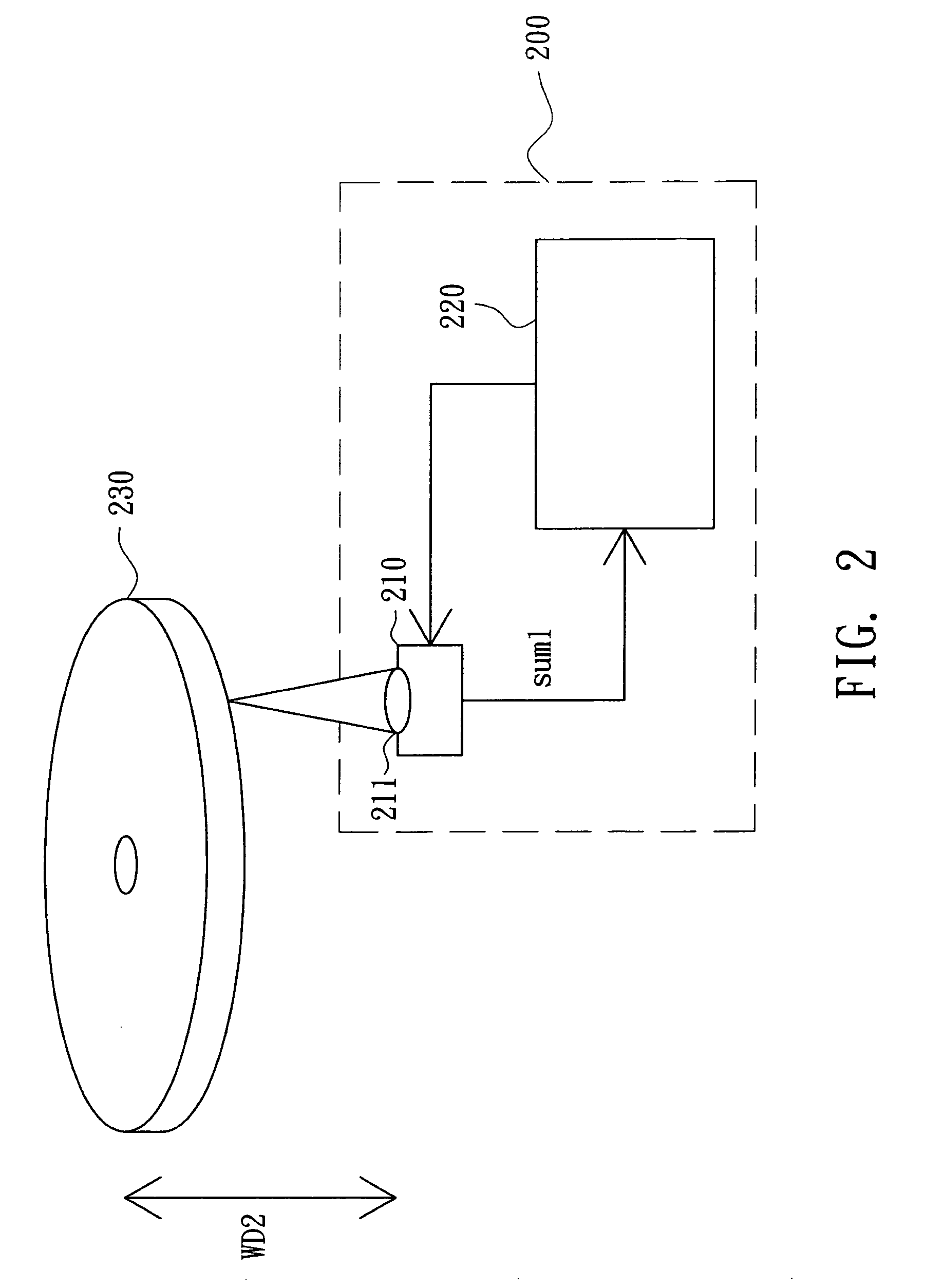
[0022] Referring to FIG. 2, an optical disk drive according to a preferred embodiment of the invention is shown. The optical disk drive 200 is for accessing a optical disk 230. The optical disk drive 200 includes an optical pick-up head 210 and a controller 220. The optical pick-up head 210 includes an objective lens 211. The distance between the optical disk 230 and the objective lens 211 is defined as a working distance WD2. Examples of the optical disk 230 include a Blu-ray Disk (BD).
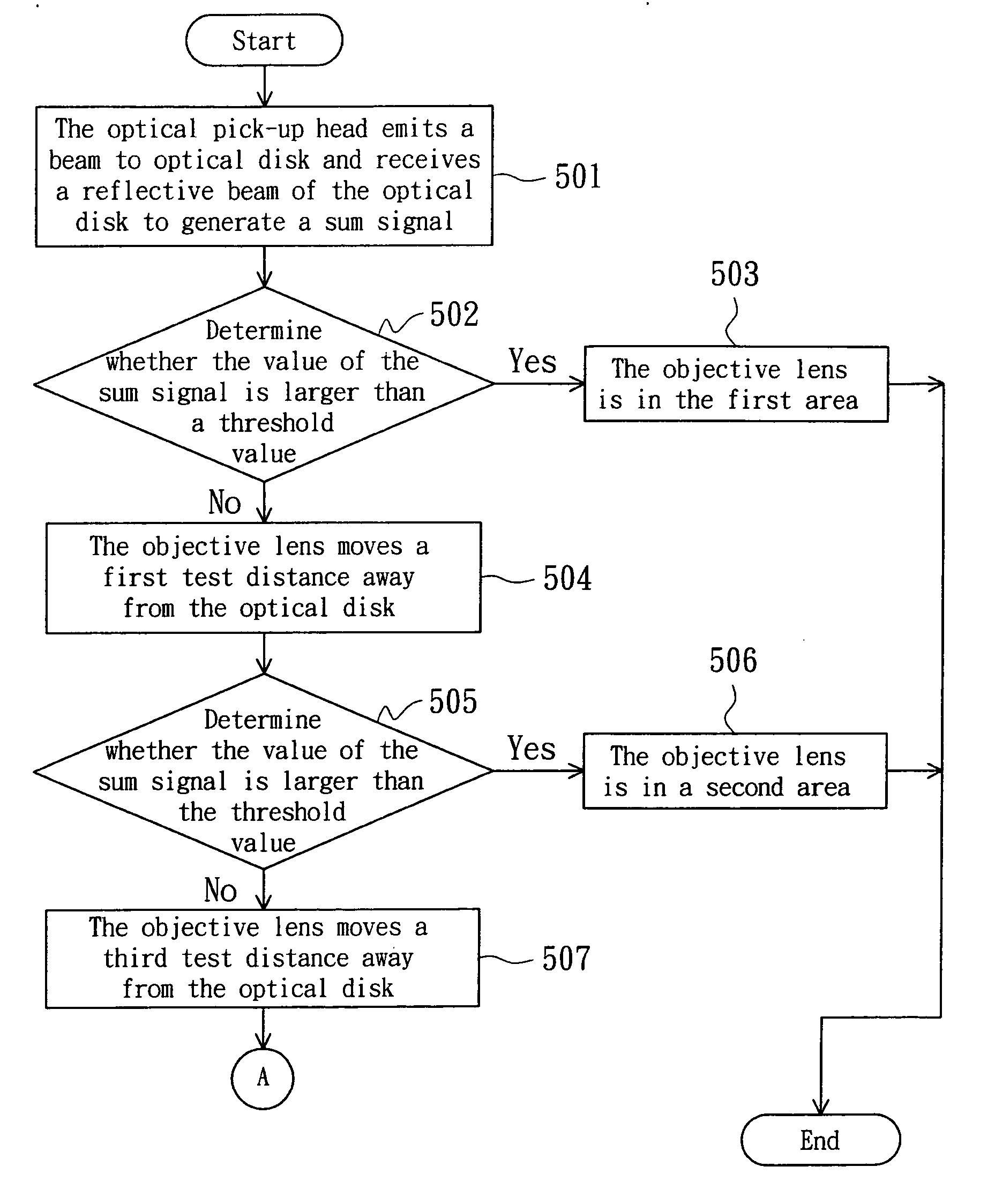
[0023] Referring to FIGS. 3A˜3C, a photo-detector of the optical pick-up head 210 is shown. The photo-detector is disposed in the optical pick-up head 210. The photo-detector has sub-photo-detectors A, B, C and D. The sub-photo-detectors A, B, C and D respectively generate a signal VA, a signal VB, a signal VC and a signal VD according to the beams respectively received by the sub-photo-detectors A, B, C and D. The value of the focus error signal Fe is expressed as follows:
Fe=(VA+VB)−(VC+VD);
[0024] In FIG. 3A, when the optical disk 230 and the objective lens 211 are correctly focused, the light point imaged on the photo-detector is circular, meanwhile, the value of the focus error signal Fe is zero. In FIG. 3B, when the distance between the optical disk 230 and the objective lens 211 is too close, the light point imaged on the photo-detector is oval, meanwhile, the value of the focus error signal Fe is smaller than zero. In FIG. 3C, when the distance between the optical disk 230 and the objective lens 211 is too large, the light point imaged on the photo-detector is oval, meanwhile, the value of the focus error signal Fe is larger than zero.
[0025] Referring to FIG. 3D, a diagram of the value of the focus error signal Fe vs. the working distance is shown. The shape of the relationship curve looks like an “S” and is therefore referred to as S-curve. In FIG. 3D, when the settings are as in FIG. 3A, the distance is defined to be 0; when the settings are as in FIG. 3B, the distance falls within the range of −0.1 mm to 0 mm; and when the settings are as in FIG. 3C, the distance falls within the range of 0.1 mm to 0 mm. When the distance is larger than 0.1 mm or smaller than −0.1 mm, the value of the focus error signal Fe approaches zero.
[0026] Referring to FIG. 4, relative positions between the objective lens of the invention and the optical disk are shown. With regard to the ideal working distance WD, that is, the distance from 0 mm to −WD in FIG. 4, normally an assembly tolerance is assigned to the working distance with the upper limit being +a and the lower limit being −b. This implies that the objective lens 211 complies with the standards as long as the objective lens 211 is within the range from +a to −b. On the contrary, if the objective lens 211 is outside the range from +a to −b, the working distance WD2 has to be adjusted. Therefore, when the objective lens 211 is in area I, area II, area III and area V, the working distance WD2 complies with the standards. When the objective lens 211 is in area IV and area VI, the working distance WD2 does not comply with the standards.
[0027]FIGS. 3A-3C show the state when the objective lens 211 is in a first area I. The S-curve of focus error signal Fe illustrated in FIG. 3D corresponds to the state when the objective lens 211 is in the first area I. The value of the sum signal sum1 is defined as (VA+VB+VC+VD). Within the first area I, the value of the sum signal sum1 is larger than a threshold value Th, and such characteristics may be used to determine which area the objective lens 211 is in, such that the range of the working distance WD2 is obtained for subsequent adjustment.
[0028] Referring to FIGS. 5A and 5B, are a flowchart of a method for determining the working distance according to a preferred embodiment of the invention is shown. Firstly, the method begins at step 501, the optical pick-up head 210 emits a beam to an optical disk 230 and receives a reflective beam of the optical disk 230 to generate a sum signal sum1. The objective lens 211 of the optical pick-up head 210 is in an initial position.
[0029] Next, proceed to step 502, whether the value of the sum signal sum1 is larger than the threshold value Th is determined. If yes, proceed to step 503, the objective lens 211 is in the first area I, otherwise proceed to step 504, the objective lens 211 moves a first test distance away from the optical disk 230. Referring to FIG. 4, the objective lens 211 moves a distance of “b” from the initial position in a direction away from the optical disk.
[0030] Next, proceed to step 505, whether the value of the sum signal is larger than the threshold value Th is determined. If yes, proceed to step 506, the objective lens 211 is in a second area II and the method is terminated, otherwise proceed to step 507, after the objective lens 211 returns to the initial position, the objective lens 211 moves a third test distance in a direction away from the optical disk 230. Referring to FIG. 4, the objective lens 211 moves a distance WD from the initial position in a direction away from the optical disk 230. Therefore, the third test distance is larger than the first test distance. Afterwards, proceed to step 508, whether the value of the sum signal sum1 is larger than the threshold value Th is determined. If yes, proceed to step 509, the objective lens 211 is in a fourth area IV, and the method is terminated. If the objective lens 211 is in the fourth area IV, the working distance WD2 does not comply with the standards and needs to be adjusted.
[0031] If the value of the sum signal sum1 is determined to be not larger than the threshold value Th in step 508, then proceed to step 510, after the objective lens 211 returns to the initial position, the objective lens 211 moves a second test distance towards the optical disk 230. Referring to FIG. 4, the objective lens 211 moves a distance of “b” from the initial position in a direction towards the optical disk 230. Next, proceed to step 511, whether the value of the sum signal sum1 is larger than the threshold value Th is determined. If yes, proceed to step 512, the objective lens 211 is in the third area III.
[0032] If the value of the sum signal sum1 is determined to be not larger than the threshold value Th in step 511, proceed to step 513, after the objective lens 211 returns to the initial position, the objective lens 211 moves a fourth test distance towards the optical disk 230. Referring to FIG. 4, the objective lens 211 moves a distance of “a” from the initial position in a direction towards the optical disk 230. Therefore, the fourth test distance is larger than the second test distance. Next, proceed to step 514, whether the value of the sum signal sum1 is larger than the threshold value Th is determined. If yes, proceed to step 515, the objective lens 211 is in a fifth area V, otherwise proceed to step 516, the objective lens 211 is in a sixth area VI. If the objective lens 211 is in the sixth area VI, the working distance WD2 does not comply with the standards and needs to be adjusted.
[0033] Compared with the conventional method of measuring working distance, the optical disk drive and method of determining working distance disclosed in the above embodiment of the invention avoid the error caused due to the accumulation of tolerance. The accumulation of tolerance may cause the objective lens to collide with the optical disk and result in permanent damages. According to the concepts of the invention, the working distance is directly measured without checking the height tolerance of the parts or inspecting the parts-feeding process, hence reducing the manufacturing cost.
[0034] While the invention has been described by way of example and in terms of a preferred embodiment, it is to be understood that the invention is not limited thereto. On the contrary, it is intended to cover various modifications and similar arrangements and procedures, and the scope of the appended claims therefore should be accorded the broadest interpretation so as to encompass all such modifications and similar arrangements and procedures.

PUM

no PUM

Description & Claims & Application Information

We can also present the details of the Description, Claims and Application information to help users get a comprehensive understanding of the technical details of the patent, such as background art, summary of invention, brief description of drawings, description of embodiments, and other original content. On the other hand, users can also determine the specific scope of protection of the technology through the list of claims; as well as understand the changes in the life cycle of the technology with the presentation of the patent timeline. Login to view more.

Similar technology patents

Semiconductor memory device and refresh period controlling method

InactiveUS20050281112A1Improved temperature compensationCost reductionError detection/correctionCode conversionError ratioRate measurement
Owner:PS4 LUXCO SARL

Classification and recommendation of technical efficacy words

  • Cost reduction
  • Avoid error

Reconfigurable platform management apparatus for virtual reality-based training simulator

InactiveUS20120122062A1Cost reductionReduce riskEducational modelsSimulatorsDriving simulatorTraining simulation
Owner:ELECTRONICS & TELECOMM RES INST

People also interested in

Why Eureka
Try Eureka